Continue to Site

Eng-Tips is the largest engineering community on the Internet

Intelligent Work Forums for Engineering Professionals

  • Congratulations waross on being selected by the Eng-Tips community for having the most helpful posts in the forums last week. Way to Go!

Aluminum Weldment Design Help 4

Status
Not open for further replies.

Andre3

Mechanical
Mar 2, 2019
53
I have recently moved from a mechanical design role into engineering at my small R&D company figured I would try reaching out to you folks for some help and direction as I do not have other colleges to consult with. I am looking to design a weldment between two 6061-T6 components supporting a very strong solenoid magnet. This had been a bolted connection but the bolts failed after the system was overloaded and now we would like to weld them together for a stronger, permanent connection. My thought was to chamfer the parts to make for a groove weld to hold them together but I am mostly unfamiliar with weldment design.

From what I have seen it looks like to be conservative I can expect the welded area to behave like 6061-O which is dramatically weaker. There is an axial magnetic force of about 250 kN downward and an outward radial force that is still being evaluated, for now I am treating it as 0.5 MPa acting on the inside wall of the support. Where should I start with evaluating the stress experienced at the weld and how it will behave? I have attached some snips of a simplified model for discussion.
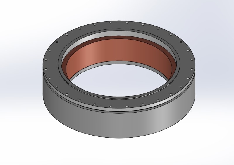
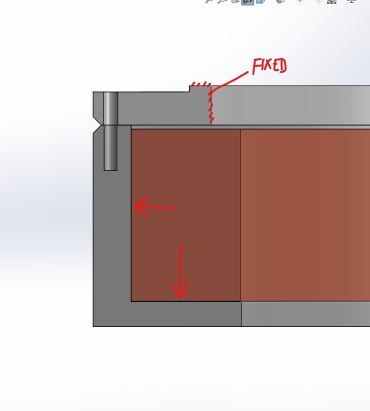
coil_and_bobbin_t3fzkh.jpg

cross_seciton_snip_mtc94x.jpg
 
Replies continue below

Recommended for you

Hi Andre3

I assume you are hoping to weld around the perimeter where the two chamfers meet ( bottom pic) left hand side.
Well the problem I see is what about the distortion that the welding might cause due to the heat input and in addition will the heat do any damage to the solenoid magnet inserted within the enclosure, from the pics it appears you can only insert the magnet prior to welding.
It might help if you can tell us in detail how the bolts failed as we might be able to help keep the bolted cover if the points I have made above are a concern.

“Do not worry about your problems with mathematics, I assure you mine are far greater.” Albert Einstein
 
Yes that was my thought with the weld geometry and I am definitely concerned with distortion and damage to the coil. We work with a good welding shop that I was hoping would weigh in on the likelihood of distortion of the cover and their ability to keep the coil cool while welding (going slow?).

There were many things at play leading to the failure of the 718 bolts that were used and I have not been able to sort it all out. The system has two of these magnet assemblies mirroring each other, the attraction force between them is about 250 kN at full current. During testing the structure failed well below its limit when the attractive force would be around 130 kN. After disassembly it was found that all of the bolts on one magnet assembly ruptured at the joint, and on the other magnet assembly half of the bolts ruptured at the joint and half pulled the helicoils out of the aluminum structure.

Some compounding issues:

The bolt preload was not controlled, tightened by hand.
Differential thermal contraction further reduced the preload.
The magnet assembly with failed helicoils had improperly short helicoils installed.
misalignment of the magnets could have been present and adding shear force to the joint.
The bolts had been reused from prior testing.
The magnitude of the radial force of the coil on the structure was not known.

The bolts should have been extremely strong, my attempts to analyze the joint still do not explain the failure at a relatively small load. We need to be completely confident in the strength of the joint moving forward so welding seemed to be the way to go.
 
@dvd Thank you, that will be useful
 
Hi Andre3

A couple of things you mention Differential Thermal Contraction? i thought it would have been Differential Thermal Expansion?. I envisaged the bolt preload being to low and the solenoid cover forcing the bolts to fail as the thing heated up.
Also you mention the bolts being extremely strong however you had failed helicoils which might suggest the threads machined into the aluminium for the helicoil installation may have failed under the combined loads as the magnets got hotter.
Just my thoughts.

Coming back to the welding I guess once those magnets are welded in there is no requirement to ever get them out?
Just looking at the section view again though there appears to be a small gap at the top between the magnet and the bolted cover so unless that gap was taken up be the coil expanding I don't see how those bolts would get loaded up or am I missing something?
I always think that when something as failed you need to understand why it did so before implementing another solution because even if you weld this cover as the weld been sized for the stresses it might see?
If you have differential thermal stresses on the weld it still might fail.

“Do not worry about your problems with mathematics, I assure you mine are far greater.” Albert Einstein
 
The magnets are conductively cooled to about 3K and don’t exceed 6K during operation. Questionable threads are definitely a possibility in contributing to the failure. I would really like to understand the failure better but given all of the factors it seems like a definitive quantitative answer is out of my reach. Is it possible for the bolts to be unevenly loaded enough that that quickly ‘unzip’, failing one at a time from taking a large percentage of the total load?

The magnets will not need to be removed so welding is okay there. The cover is fixed in place by more structure that is not shown and the coil is applying a force downward, putting the bolts in tension. There is a g10 spacer on top of the coil filling that gap also but it is not shown in that simple model.
 
Without making any other changes the resilience of the joint could be greatly improved by drilling the bolt holes nearly through the body of the magnet and only threading the bottom. this will substantially increase the grip length of the bolt and reduce its sensitivity changes in tension due to differential thermal expansion. It's also a good practice to put a register or dowel pins to precisely locate components.
 
Just recently looked at a magnetic attraction issue on a smaller scale - the magnetic force and relatively small mass result in a big accelerations/decelerations. Is there kinetic energy being absorbed, or is loading only due to forces?
 
@Tugboateng this is very interesting, I would think that would reduce the stiffness of the bolts. I will have to think more about it to understand how that would help. I definitely would add pins if we go to using bolts again, it would help with the shear force also.

@dvd the magnet does not move and is ramped very slowly, I have thought of it as quasi static forces.
 
If you go the pin route hollow pins on existing bolt holes would have little effect on design. A register would provide the best shear resistance, though.

Think of the bolt as a spring. Your differential expansion is fixed. The bolt will see the same change in length whether it's long or short. However, with a longer bolt the change in strain will be less as increasing the length is in the denominator of the strain unit.
 
I hadn’t realised the coils were cooled so low, why so low assuming Have read your post correctly 3K is according to my Celsius scale -270deg C is that correct?
I see why you said thermal contraction contraction now (lol). Yes it is very likely the bolts could be unevenly loaded and fail one at a time, I saw this happen once on a crane cab slewing gear where 48 bolts unzipped, I didn’t believe it at first but I saw all the evidence.
If the bolts weren’t controlled when tightened to achieve an equal preload then that could be a source of the problem and I have to say torquing the bolts would still produce a very uneven preload in each bolt because torquing bolts can be inaccurate by as much as +/- 25%.
The other thing here at such low temperatures what about the material properties? I imagine that some materials in the assembly might go brittle at the temperatures you mention.
Something else with the welding is whether it needs stress relieving are not to remove residual stresses from the weld as these we only add to any mechanical stress the unit sees in service.

I think we need to understand more about the operation of this magnet, it’s unlikely you will get the best answers if there is information we are not aware of like the the temperature you have brought to our attention.
I agree with TugboatEng using longer bolts will help but also I would take the bolt hole and tapped hole through the base and not leave it a blind tapped hole, the reason I say this is that it will reduce the stress concentration factor at the bottom of the threaded hole which you would normally get with a threaded blind hole, however that can come later I think you need to understand the failure more first.👍

“Do not worry about your problems with mathematics, I assure you mine are far greater.” Albert Einstein
 
Andre3 said:
The bolt preload was not controlled, tightened by hand

This is a major problem. Before you go and redesign something that may not need it, you should run any quality control problems in the manufacturing process all the way to ground.
 
Bolted/flanged connections are usually avoided when possible in cryogenic systems when using permanent connections; take a look at any tank fill connection flange or 4 bolt Mueller flange in cryo service, and they will usually leak over time from thermal cycling. Also most manufacturer recommendations are to slightly re-torque when assembly is cold.

Now to your problem. At 2-3 Kelvin I'm guessing you are working on a superconducting magnet in the vicinity of a bath of helium with subatmospheric pressures. At these ultra-low temperatures, you may have to use invar material with the bolted assembly to counteract thermal loss of fastener preload. Just a thought.

----------------------------------
Not making a decision is a decision in itself
 
Are the housing parts too large to thread one in to the other?

Ted
 
Thank you for the replies, let me give some more information.

Yes these magnets operate at 3-6 Kelvin and are cooled conductively (cryogen-free) using GM cryocoolers. The entire system is contained in a vacuum chamber and takes serval man weeks to assemble. While it is operating we have have temperature data at select locations, voltage taps, and external magnetic field measurements, otherwise we do not have feedback on what is going on inside the chambers, especially structurally. This is all for a one of kind prototype machine. Future iterations of the design will be carefully thought out for manufacturability, reliability, etc. but for now the goal is to get the magnet together, ideally very overbuilt in this problem area, and functioning so the rest of the systems can be tested.

The bolts used were Inconel 718 which remains ductile and has been used for structural components in other cryogenic systems. How a welded 6061-T6 joint will perform I am less certain of. I would prefer to chase down the exact cause of the bolt failure but I don't see how a solution could be found with the number of unknowns. If anyone has ideas on how to better asses the failure I would like to know your thoughts. What I already know:
There are no signs of fatigue on the fractured bolts.
The surviving bolts were tensile tested on our Instron to failure reaching a peak load of 27.3 kN, which is higher than the nominal ultimate strength of the M6 bolts.
The attractive force between the coils could not have exceeded 200 kN at any time by geometric constraints.

Silly things like not controlling the preload and reusing bolts I did not have a part in and wont happen again obviously.

If the strength can be be massively improved by welding then that is the way we should go to keep the project moving. I prefer bolts so the joint is not permanent and I don't need to worry about but it is not a necessity. That leaves the question that I am trying to answer to be; How strong would a welded joint like the one shown be? Maybe the better solution would be to size up the bolts and make them long? I am going to take a look at that as well.
 

@hydtools I like that idea but I don't think it would be practical in this case.
 
Andre3,

I looked very quickly at dvd's link, and it looks very useful.

When I consider designing an aluminium weldment, I assume that the welds will anneal heat treated material, making it weaker, and that the welding will cause distortion. Any critical machining must be done after welding, stress relieving, and heat treating. Soft aluminium probably is difficult to machine.

If you are bolting this together and running it at 3[°]K, you need to manage differential thermal contraction. You could use a stack of belleville washers to maintain an acceptable contact force, or you could use aluminium bolts.

--
JHG
 
Hi Andre3

If the solenoid container is made solely from the Aluminium alloy then the weld will only have the same region of strength as the parent metal,so you still need to evaluate the stresses in service and not to mention distortion post welding with solenoid in situ and or any effects of post weld stress relieving . I can’t find any information on the coefficients of linear expansion for the Aluminium alloy or the Inconel bolts at the temperatures mentioned in your design but I did find a minimum working temperature of -250 degrees C for Inconel bolts and from the information you gave above the design exceeds that limit at 270 degrees C.
The bolt failures, some of which you informed us failed at the cover interface, I now believe failed in shear due to relative movement between the housing cover and body,due to differential thermal expansion on the diameter of the housing. Do you have any of the bolts? If so can you take some photographs of the failed bolts and post on here?
I can’t really comment on the bolt failures you mentioned due to incorrect helicoil installation and I am puzzled why tensile tests were done on the remaining bolts as I don’t now believe they failed in tension unless you were looking for changes in mechanical property of the bolts or testing to ensure you had what you paid for.
Below is a link for pictures of bolts failed in shear which might help


“Do not worry about your problems with mathematics, I assure you mine are far greater.” Albert Einstein
 
Status
Not open for further replies.

Part and Inventory Search

Sponsor