What I have shown is valid according to the ASME Y14.5 standard. If you follow the ISO standards, I think you won't be able to use the circled M following the datum reference in the "tolerance frame" to provide the additional variation which is called in ASME "datum shift". The MMR following the position tolerance is valid.
It makes the most sense to control the rest of the part features with profile referencing A primary, B secondary. It will control the form and size, as well as location and orientation of the surfaces with respect to the "datum reference frame"/"datum system". The all-around profile on the internal geometry was just an example. You can choose the tolerance values. If you have any features critical for function, control them with a tighter tolerance. If nothing is particularly important, you could specify a loose general profile tolerance on all surfaces, and direct to the CAD model for query for all the basic dimensions that are not specified.
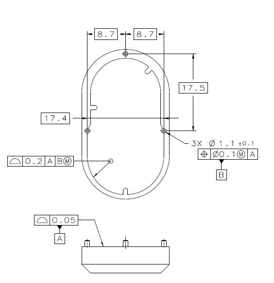
 . Btw this might be dumb question but you mentioned that you used ASME Y14.5 in the drawing but I see that you used 3X instead of 3PLACES for specifying the pins but isn't 3X iso? Is it okay to mix standards that way?