I have spreadsheets for both methods from AISC Design Guide 1 edition #2. I sent the triangular distribution method to a friend and he found an interesting situation where the anchor rod tension is negative even though e > ekern. I for the life of me cannot figure out where the error is.
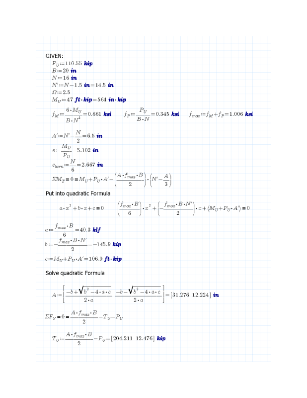
Pu = 110.55 kip
Mu = 47 kip-ft
B = 20 in
N = 16 in
N' = 14.5 in
A' = 6.5 in
fpn = 2.224ksi (nominal concrete bearing capacity)
e = Mu/Pu = 5.102 in
ekern = N/6 = 2.667 in
e > ekern, thus large eccentricity moment
A = 0.5 * (3N` ± [ (3N`)2 - 24(PuA` + Mu)/(fpnB) ]0.5)
A = 0.5 * ((43.5 in ) ± [ (43.5 in)2 - 24((110.55 kip)(6.5 in) + 47 kip-ft)/((2.224 ksi)(20in))]0.5)
A = 39.072 in ; 4.428 in (4.428 in is obviously correct one)
Tu = fpnAB/2 - Pu
fpnAB/2 = (2.224 ksi)(4.428 in)(20 in)/2 = 99.5 kip
Tu = 98.5 kip - 110.6 kip = -12.1 kip
Can't figure out why. I thought it might be an error calculating A but I have triple checked it.