Continue to Site

Eng-Tips is the largest engineering community on the Internet

Intelligent Work Forums for Engineering Professionals

  • Congratulations waross on being selected by the Eng-Tips community for having the most helpful posts in the forums last week. Way to Go!

ACI 318-14 Max Wall Reinforcement 1

Status
Not open for further replies.

bookowski

Structural
Aug 29, 2010
983
It appears that in 318-14 and later the wording for max vertical steel has changed and the 8% max rule now reads for "columns" vs 318-11 and earlier where it read "compression members". I have scoured the commentary and cannot find anything explicitly limiting the vertical steel in a wall.

I'm not looking for any commentary that the walls should be revised, or lateral system is inefficient. This is not our project. We are reviewing a project by others and it has come up as a sticking point. We are looking at a job where the walls have 10% to 12% vertical steel and the argument is that the code no longer prohibits this. Does anyone know if this is correct, and the intent of 14 and newer was to free up walls from this restriction or this was an aci wording mistake/oversight? The only argument I can make to enforce the 8% rule is that when forming the p-m diagram for walls we do it based on the same principles and equations that we use for columns, so it seems that the restrictions of columns may apply (although we know that this isn't the case for all wall vs column detailing rules so maybe not).
 
Replies continue below

Recommended for you

When ACI 318 was completely reorganized in the 2014 version, I'm sure that they did not intend to remove the 8% maximum reinforcing limit for walls. It does appear, though, that if you are following the code as it is now written that the limit "technically" would not apply. Your P-M diagram argument wouldn't actually work since the principles and equations for this are now found in Chapter 22 (Sectional Strength) instead of Chapter 10 (Columns).

That said, the limit of 8% was set since that is considered to be a practical limit for placing the concrete. I don't see any reason why a wall should be treated differently than a column for this.

Structural Central
 
1) I can't claim to know ACI's intent on this one.

2) I can think of one difference between walls and columns that might justify different treatment for the two: closed ties. With closed ties and normal, "column-ish" proportions, a lot of your splicing ends up being about moving the upper bars inwards concentrically. And that affects congestion and bursting tendencies. With uniformly spaced wall bars, I feel that this is less critical and one might be able to study a given situation, possibly with the aid of the concrete supplier, to determine if high reinforcing ratios would still cause placement issues.

3) If this is tied zone reinforcement, I'd like to stick to the 8% rule. If it's distributed wall reinforcement, I might be willing to consider higher reinforcing ratios. That said, >8% as distributed sure does sound like a crap ton of reinforcing in a wall. I'd want to study both the design of the wall and scaled sketch of what that looks like to gauge overall nuttiness.

4) If those bar are used in compression at such high reinforcement, there's a pretty good chance that even distributed wall bars would need to be tied. Those ties might affect how the splicing is done and, thus, one's level of comfort with the setup. So as not to splice concentrically but still get ties over bar splices, perhaps offset splices would be best.

Questions for you:

a) Are we talking about zones or distributed wall steel?

b) Are these bars to be active in compression?
 
The commentary to 318-11 reads:

"Maximum reinforcement — Extensive tests of the ACI column investigation included reinforcement ratios no greater than 0.06. Although other tests with as much as 17
percent reinforcement in the form of bars produced results similar to those obtained previously, it is necessary to note
that the loads in these tests were applied through bearing plates on the ends of the columns and the problem of trans-ferring
a proportional amount of the load to the bars was thus minimized or avoided. Maximum ratios of 0.08 and
0.03 were recommended by ACI Committee 10510.26 for spiral and tied columns, respectively. In the 1936 Code, these limits
were made 0.08 and 0.04, respectively. In the 1956 Code, the limit for tied columns with bending was raised to 0.08.
Since the 1963 Code, it has been required that bending be considered in the design of all columns, and the maximum
ratio of 0.08 has been applied to both types of columns. This limit can be considered a practical maximum for reinforce-ment
in terms of economy and requirements for placing."

So it appears that part of the concern is ensuring the assumed load proportioning and transfer.

For placement they reference a "practical" max on economy and placement, but presumably economy is none of their business and the other placement rules can be satisfied at ratios above 8%. If you're using #11s you can still get about 2 bar diameters clear with 8% (less at the couplers, but probably ok if staggered). If you are using larger diam bars then things get better.


Distributed bars, but these are large high strength bars like #24 so this is better in terms of congestion. It's more like a composite type system, with huge chunks of steel spaced somewhat further apart than you'd imagine these ratios.

I think these are primarily for tension, but don't know enough of the original design/demands to be sure that it isn't also at least partially required in compression.

As I play devils advocate I'm starting to think it's probably ok.
 
bookowski said:
So it appears that part of the concern is ensuring the assumed load proportioning and transfer.

In this respect, I would think that you'd be in pretty good shape for a shear wall since the axial loads would be introduced into the rebar very gradually starting at the top of the building. Same for any gravity element that picks up load gradually over the height if the building I suppose.
 
Congestion would be particularly bad at laps; 12% vertical steel becomes 24% at laps, unless laps are staggered.

BA
 
Kootk said:
you'd be in pretty good shape for a shear wall since the axial loads would be introduced into the rebar very gradually starting at the top of the building
Agreed, again why I'm starting to think it's probably not so bad. I'm also becoming somewhat impressed that someone managed to find this change in wording and take advantage of it. I probably wouldn't have done it myself.

BAretired said:
Congestion would be particularly bad at laps; 12% vertical steel becomes 24% at laps, unless laps are staggered.
There are no lap splices on the large diameter bars, they are always mechanically coupled so the 12% stays at 12%.

 
A_steel = 8% is pretty darn congested, even with no splices.
A_steel = 12% and now you're getting pretty far from common practice.
The couplers are about 2x the bar diameter, and you can only stagger the couplers so much because there are so many bars.
Keep in mind that at floor locations, horizontal bars need to pierce your vertical rebar fortress in multiple locations.
Theoretically possible. Hopefully you have the A+ team for ironworkers.

I suggest you draw some of your wall-floor details to scale (bars with deformations) in the plan view and side view. Make sure to show all the cross ties, vertical bars, and horizontal bars in the crossing planes. You might indeed observe some "nuttiness" (per Koot) and change your mind.
If you pull off the 12% trick, please share the photos with us. In fact, I will buy you a cheeseburger. It will be a sight to behold.
 
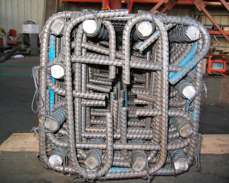
For reference, the column rebar cage image pasted below is approx As_long't = 4%
Hopefully you're using high slump concrete with small aggregate. Navigating a vibrator head down that steel forest will be a challenge.

Rebar_congestion_in_column_q1bg1f.jpg
 
Just because you can, doesn't mean you should. Constructability issues, installation tolerances should be considered.

Can you provide a bit more information on what this element is?
How thick is the wall?
Is this at the base of a tall building and is this triggered by not having enough dead load to counteract the flexural tension?
Can higher grade of reinforcement (Gr 80 or Gr 100) be used to alleviate rebar congestion?
 
I would also be interested in hearing the application for this wall.

I have heard of structural engineers considering a transformed moment of inertia for shear walls in high rise design. At 12% steel, that would be a non negligible increase to I.
 
We are looking at a job where the walls have 10% to 12% vertical steel and the argument is that the code no longer prohibits this.

I'd question that argument. From a design standpoint, you'd be talking a overreinforced section. I've looked at a lot of existing members like that (done long ago by working stress design) and it's like a lot of that excess steel isn't even there (from a design standpoint).

And I'd be darn careful how this would be used seismically. (Unless the R value was cut to something like 1.)

 
WARose said:
I'd question that argument.
OK, but if you're going to question an argument of is this technically allowed by code it seems that it should be backed up by some code excerpt (or relevant commentary). It doesn't make much sense to say that you disagree that it is technically allowed by code with the argument being that it seems like a bad idea.

ATSE said:
For reference, the column rebar cage image pasted below is approx As_long't = 4%
That column congestion appears primarily from the ties, and are those #6 ties? I don't think that's a good comparison. We often do walls that are 4% to 8% with couplers and in the field they never look as bad as I'd expect. I agree that at 12% it probably looks odd, but with large diameter bars you get decent spacing and most structures at this scale look a bit nuts. Either way the question here is whether or not it's allowed, so scary picture or not doesn't settle it. Again, this is not our project so I can't get your free cheeseburger unless you're just feeling particularly generous.

slickdeals said:
Can you provide a bit more information on what this element is?
It's a shearwall, very thick. I won't get into too much detail as its not our project, we are only reviewing it and this came up (not because of any problem or issue). It's a very tall building, yes they use the transformed section (and cracking) but this is common even at lower percentage, very low seismic, high wind, rebar is this high for tension (flexural and net). These are all high strength large diameter coupled bars.


I'm not so interested in the should you do this advice. I was just making sure that I did not miss some code errata or that they buried this somewhere else now. Based on the lack of any code references prohibiting this it seems like it's a reasonable reading of the code that it is technically allowed.


OK, but if you're going to question an argument of is this technically allowed by code it seems that it should be backed up by some code excerpt (or relevant commentary). It doesn't make much sense to say that you disagree that it is technically allowed by code with the argument being that it seems like a bad idea.

Fair enough.....but the point is: it's moot. What are you going to do with all that excess steel? (Maybe deflection control? Can't imagine a wall needing that.) It just sounds like a waste of material.

And technically it is prohibited by code as code prohibits overreinforced sections. (Assuming the layout puts a lot of this steel in the tension zone under flexural loads.) The allowable strains in the code result in a reinforcing limit of about 0.75ρb. That's never going to result in % of steel you are talking about here. (EDIT: Unless compression steel is considered here.....something I am not clear on. And in that case, the vertical steel would have to be tied....something you don't see too much in wall steel....except at boundary elements.)
 
As far as i understand ,there is an implicit limitation which is the constructability limit . If in a wall longitudinal reinforcement exceeds 0.01Ag, then Section 11.7.4.1 of ACI 318-14 applies .

(11.7.4.1 If longitudinal reinforcement is required for axial
strength or if Ast exceeds 0.01Ag, longitudinal reinforcement
shall be laterally supported by transverse ties. )

Just curious, if longitudinal reinforcement Ast 12 %, can you show us with a sketch etc.how the requirement 11.7.4.1 will be satisfied?

IMO, if the longitudinal reinforcement Ast greater than 4 %, the use of steel plate shear walls or Composite steel plate shear walls should be considered for economy and constructability .

The following fig . is for typical Composite steel plate shear wall (from Seismic Behavior and Design of Composite Steel Plate Shear Walls)

composite_shear_walls_j28mbd.jpg


WARose said:
it's moot. What are you going to do with all that excess steel? (Maybe deflection control? Can't imagine a wall needing that.) It just sounds like a waste of material.
They want to make sure they will be able to stick fridge magnets to the shearwalls. The building has lots of kids and they thought this would be a nice amenity. I don't know what you mean by "all that excess steel" and a "waste of material" - they aren't just dumping old steel they need to get rid of into the walls, presumably none of it is excess and it's working very hard which is why they were forced to put this much steel in there.

HTURKAK said:
11.7.4.1 If longitudinal reinforcement is required for axial
strength or if Ast exceeds 0.01Ag, longitudinal reinforcement
shall be laterally supported by transverse ties.
That was revised in the errata to '14 to be consistent with earlier 318's and changed to "and". In this case however they are tying the bars and I don't see that implicitly forbids the max steel. You don't count your tie steel towards your percentage of vertical steel. Think #24 bars spaced on a grid 8" o.c. each way, multiple rows, in 36" thick walls and you get the idea. no need for a sketch. Spacing limits are met. Steel plate shear walls are neat but again, once it gets into the "IMO" it implies that there is no code restriction here (unless buried in the commentary it offers a restriction based on imo's of internet dudes).


They want to make sure they will be able to stick fridge magnets to the shearwalls. The building has lots of kids and they thought this would be a nice amenity.

[thumbsup2] Good one.

I don't know what you mean by "all that excess steel" and a "waste of material" - they aren't just dumping old steel they need to get rid of into the walls, presumably none of it is excess and it's working very hard which is why they were forced to put this much steel in there.

I assume then the vertical steel in the wall is tied? If it isn't, then (unless it is there for deflection purposes).....the magnet theory may be as good as any.

You said yourself that "...[you] don't know enough of the original design/demands to be sure that it isn't also at least partially required in compression..."....so if you don't know what the demands are.....it's just as hard for us.
 

- I do not see the errata to '14' if you post the relevant excerpt , i would be happy.

- My interpretation of item 11.7.4.1 is, longitudinal reinforcement must be supported by transverse ties , that is, a tie bar would be provided at every intersection of longitudinal and transverse reinforcement which would increase the labor cost .

- I got the picture of ( #24 bars spaced on a grid 8" o.c. each way, multiple rows, in 36" thick walls )..#24 bar diameter is 24=3*8/8= 3 in. ( 76 mm )..The mechanical couplers in the market ( in my zone ) is for up to 50mm dia. and for 76 mm could be custom product.

-The maximum reinforcement ratio for columns is 0.08Ag. Although the maximum reinforcement ratio for walls not explicitly stated, this should not mean to circumvent the past experience and column limitations.

 
Status
Not open for further replies.

Part and Inventory Search

Sponsor