Tek-Tips is the largest IT community on the Internet today!

Members share and learn making Tek-Tips Forums the best source of peer-reviewed technical information on the Internet!

  • Congratulations TugboatEng on being selected by the Eng-Tips community for having the most helpful posts in the forums last week. Way to Go!

A question about plate splice

Status
Not open for further replies.

tmgczb

Structural
Joined
May 12, 2021
Messages
176
Location
CN
%E5%BE%AE%E4%BF%A1%E5%9B%BE%E7%89%87_20221225210307_hcfdgi.png

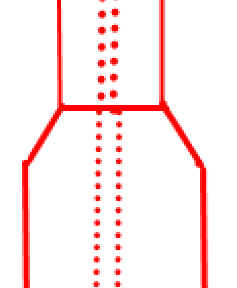
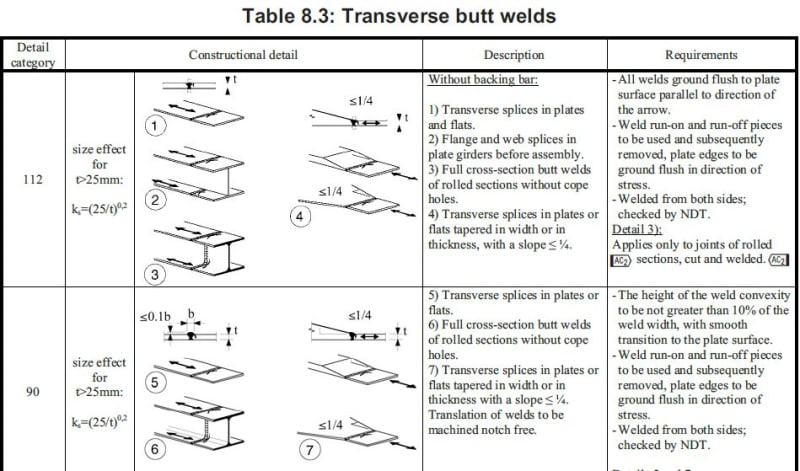
What is the required slope in the splice of flange plates of different width, 1:6 or 1:4?
 
I cannot understand the question... Can you have more lines of fasteners?

-----*****-----
So strange to see the singularity approaching while the entire planet is rapidly turning into a hellscape. -John Coates

-Dik
 
This is a welded splice connection, but top part is narrower than the bottom part.
To avoid a sudden change of member section, there shall be a piece to make it change smoothly.
 
well, if it was an aircraft part, I would make it at least 1:10, and then calculate the Kt at the end of the taper and apply that Kt to the stresses to calculate margins of safety.

presumably the dots are actually dashes showing the web of an I-section, and not fasteners ???
 
1) why are there different widths of the splice plate ?

2) why not use straight tapered sides (a trapezoid) ?

3) what is the loading on the underlying structure ? a beam in bending ? a web in shear ? a web in tension ??

4) what do the dots mean ? not fasteners if welding ??

"Hoffen wir mal, dass alles gut geht !"
General Paulus, Nov 1942, outside Stalingrad after the launch of Operation Uranus.
 
Status
Not open for further replies.

Part and Inventory Search

Sponsor

Back
Top