Continue to Site

Eng-Tips is the largest engineering community on the Internet

Intelligent Work Forums for Engineering Professionals

  • Congratulations KootK on being selected by the Eng-Tips community for having the most helpful posts in the forums last week. Way to Go!

432 Park ave. - NYC

Status
Not open for further replies.

XR250

Structural
Jan 30, 2013
5,992
Just got back from a trip to NYC. How amazing!
Anyhow, I was researching the structure of 432 Park Ave. and Wiki says its core is only 30' x 30'. Seems kind of spindly for a 1400 ft. tall building. Are they somehow using the exterior concrete walls to help provide stability?
 
Replies continue below

Recommended for you

Based on the column sizes in wiki (and the core walls being "only" 30 inches), I would guess they're using outriggers to grab on to the exterior columns at certain levels.
 
I was there for the first time in October and was equally impressed by that one.

My research indicates that you're both right. It's a perimeter moment frame tube coupled to the core at each of the five, two storey open levels. That coupling must be done by way of some manner of outrigger but I've yet to find a good picture or description of that. My hotel was near there and, when we'd leave for the day, I'd stare into those open levels looking for a wall or truss to satisfy my curiosity. Maybe Bookowski or one of the other natives can enlighten us.

I like to debate structural engineering theory -- a lot. If I challenge you on something, know that I'm doing so because I respect your opinion enough to either change it or adopt it.
 
Link
Link

Easy googling results for the curious.

I like to debate structural engineering theory -- a lot. If I challenge you on something, know that I'm doing so because I respect your opinion enough to either change it or adopt it.
 
Must be alot of shear going thru those outriggers
 
I don't care what the engineer says when a building gets that tall and that extreme of an aspect ratio, I just call it scary skinny. Even with tuned mass dampers I wonder what its sway is like in a high wind event.

A confused student is a good student.
Nathaniel P. Wilkerson, PE
 
Some random results of trolling. If it's the two storey concrete walls shown, and they're outboard of the core, it would seem to be virtual outriggers.

I can get behind the superstructure design for these things but still find the foundation overturning design aspects to be astounding.

IMG_0370_zpzsd3.png

IMG_0369_jxkd12.png

IMG_0367_gxmfzv.jpg

IMG_0368_zrpyip.jpg


I like to debate structural engineering theory -- a lot. If I challenge you on something, know that I'm doing so because I respect your opinion enough to either change it or adopt it.
 
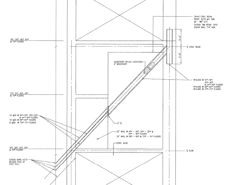
I have the superstrucure drawings for that one but not the foundation unfortunately. Just took a look and info above looks correct. The core is up to 2'-10" thick, 14ksi, and perimeter columns are huge (36" x 44" for example). Slabs look like 10" or 12" and cambered. There are large embedded steel shapes at various locations. Couldn't make sense of all of them with a quick look but I did see that at the outrigger levels there are embedded wf columns in the verticals and steel beams in the outriggers. The outriggers don't appear to ever be solid, as far as I can tell there is always at least one door punched through. Some outriggers have a weird detail with steel wf beams in the horizontal and then vertically connected between floors with rebar to welded couplers on the wf beams. Other outriggers have a wf diagonal brace. I don't want to post the drawings for fear of some wsp groupie yelling at me. Doesn't look like any magic though, just huge members from high strength concrete, outriggers, and a tmd.

Drifts must be quite high but the tmd would take out the acceleration so in theory you don't freak out.
 
Embedded structural steel is reasonably common for improving shear strength when up against the concrete limit. Getting a lot of traction in high seismic areas. West coast will use wide flanges embedded in their coupling beams as there's a fair amount of testing for it that was done at UCLA, final reports are available from Pankow Foundation for the curious. Have also seen just steel plates used which improve shear performance without also dramatically increasing coupling beam flexural strength (and thus increasing shear demand) like embedded wide flanges will. Not as much research though and most (all?) of it out of Hong Kong, so not as widely used in the US as the wide flange approach.

Have to pay more attention to anchorage though. Usually not thought of as much for concrete but when you're getting much stronger in the links you'll need anchorage capable of transferring that force to the walls and even may need to be beef up the walls (especially locally) so that you don't have a strong beam-weak wall mechanism. Would assume that's not nearly as big a concern in New York. Steel columns could be embedded in walls for that reason or could be there simply because you need a whole column's worth of welded bars and/or studs to get your force transferred. Our office has done that when transferring load between steel and concrete elements where the forces were just so large that we used embedded steel shapes to help us spread the load transfer out over a larger area.
 
Thanks to everyone for the info
 
MrHershey - Thanks for the pankow heads up, just downloaded those papers. Good stuff.

I see both steel plate and wf used around here. I've never fully mentally resolved the plate only option, I see people using that to resist the shear and the concrete beam to resist the flexure w/out any consideration of the interaction. Since the shear and moment are two parts of the same this doesn't make sense. I'm sure it can be detailed but needs some thought. I stick with the wf.

Here's an example of one of their outriggers. This is from a dd level set so maybe this became more sensible down the road. Looks a bit sketchy as shown. If you can't read it that is a 14x550 embedded at the right! The detail where the wf turns into rebar....

park_outrig_yhuqb6.png
 
There's calculations to be done for the interaction. At least what we've seen is steel plate has headed studs welded both sides so it acts compositely. A bit lighter stud distribution over the span and then heavy distribution at the ends when transferring to adjacent wall. A lot of the wide flange coupling beams won't use studs at all as they rely on a bearing couple at the ends for transmitting force to the side walls. Then just have to embed far enough so you have a long enough lever arm to keep bearing forces manageable.

That screenshot looks similar to what we've done when marrying steel to concrete with a large force transfer. Just a lot to transfer in one spot so we'd embed structural steel to help spread the load transfer out over a bigger area.
 
Status
Not open for further replies.

Part and Inventory Search

Sponsor