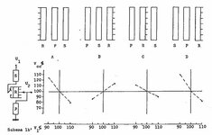
I have the following data for a 3-winding transformer
S = 350/350/100 MVA (HV/LV/TV)
U = 410/230/36 kV (HV/LV/TV)
OLTC range: +/-12x1.5% located at HV side
Z(HV-LV) nominal tap = 13% @350
Z(HV-LV) max. tap = 14% @350
Z(HV-LV) min. tap = 13% @350
Can any transformer expert determine the ratio value corresponding to an impedance of 14%? Will it correspond to 483.8/230 or perhaps 336.2/230?
Logic tells me that the 14% will correspond to 483.8/230, due to the greater number of turns, but why then is the impedance for the minimum tap equal to the rated impedance?

