Continue to Site

Eng-Tips is the largest engineering community on the Internet

Intelligent Work Forums for Engineering Professionals

  • Congratulations waross on being selected by the Eng-Tips community for having the most helpful posts in the forums last week. Way to Go!

24" x 24" precast columns with (4) #11 vert reinforcement 5

Status
Not open for further replies.

Prestressed Guy

Structural
May 11, 2007
390
For 24" square precast columns I would prefer to use (4) #11 bars (ρ = 1.08%) due to the simplicity of the cage with no need for crossties. When I run it in Bentley software with seismic provisions checked it comes out as a good design.

I mentioned that to another engineer and his response was "you can't use a 24" column with only 4 bars in seismic design (SDC D). When pressed he could not sight a reason but was adamant about not using (4) #11 bars.

Opinions? Yes / no and why.
 
Replies continue below

Recommended for you

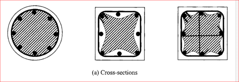
Those three cross sections on the left of the image are taken at the ties. Between ties is less confined. Though, for your 6" tie spacing, it would hardly change. What drives that tight spacing?

Edit: what's the length of the precast column? I want to compare to Aust code and we have extra requirements depending on column clear height.
 
Vertical bars are primarily stressed in compression and would buckle outward if not tied. Ties prevent vertical bars from buckling. Ties are stressed in tension. The concept of vertical bars providing confinement to the concrete is wrong! Without ties, the vertical bars would simply push the outer concrete cover away from the core, reducing the concrete area. The only confinement provided to the inner core is provided by ties, not vertical bars.

BA
 
The only confinement provided to the inner core is provided by ties, not vertical bars

Confinement is provided by the bends in the ties, which have longitudinal bars in them. If there were a horizontal limitation on spacing of confinement tie-bends, that would implicitly limit the longitudinal bar spacing. There doesn't seem to be such a limit which seems odd to me.
 
steveh49 said:
Confinement is provided by the bends in the ties, which have longitudinal bars in them. If there were a horizontal limitation on spacing of confinement tie-bends, that would implicitly limit the longitudinal bar spacing. There doesn't seem to be such a limit which seems odd to me.

Concrete in a column is not significantly confined by reinforcement. When concrete is confined, its compressive strength goes up by a factor of 3 or more. Column ties prevent vertical bars from buckling. That is their purpose and that is all they are intended to do. They manage the job quite well in a square column with four corner bars.

BA
 
Confined concrete is more ductile, but I agree that minimum confinement such as being discussed does little but restrain the reinforcement (a minimum level of ductility). I'm just curious why there's a (seismic) requirement for close-spaced ties to restrain the reinforcement but no requirement in relation to the concrete which is carrying the majority of the load. I think the Aust code is similar. OTOH, Agent666 and Hturkak have said their codes are more stringent so maybe ACI/AS just lagging.

BTW that image I posted shows square columns. The confined part of the cross section would be smaller for rectangular columns and could be quite a small part of the total area.
 

The spacing of longitudinal reinf. is limited at some codes and recommended practices but for seismic design . In your case if the subject columns are not part of SFRS , you may feel free and follow ACI 318 strictly.

Some code references;

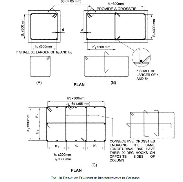
- When you write IS 13920-2016 ( it is free ) you can see the following snip ;

IS_13920_eobuzd.jpg


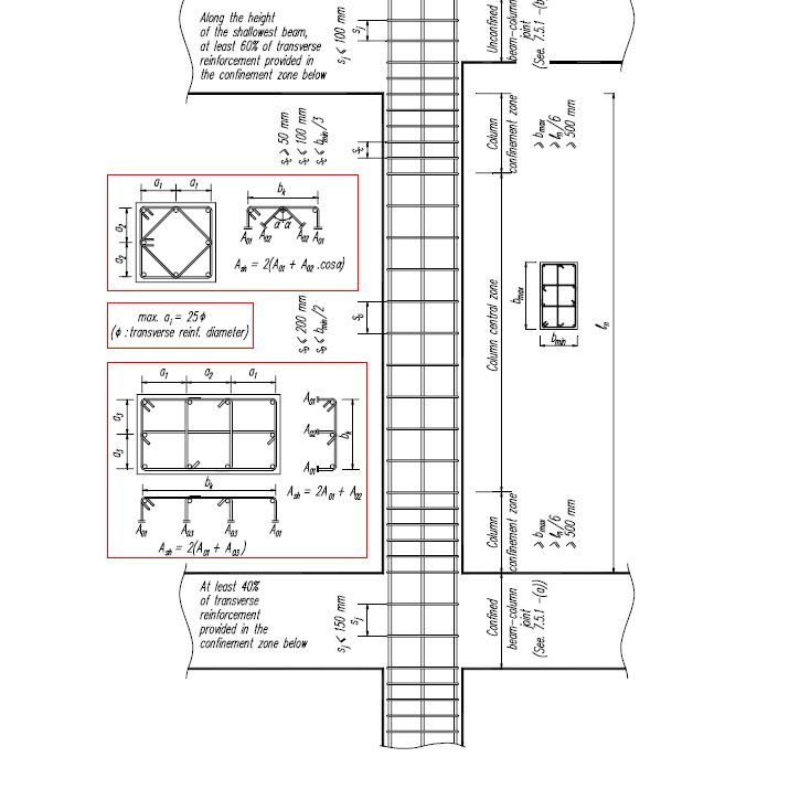
- Another snip from other code ,

DBYYHYENGCOLUMNDETAIL_q5jkdn.jpg


- Excerpt from Recommended practice NIST GCR 8-917-1,

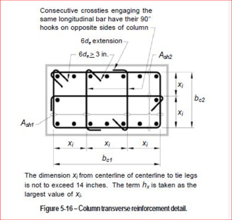
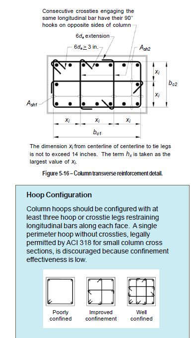
As shown in Figure 5-16, ACI 318 permits the horizontal spacing between legs of hoops and crossties to be as large as 14 inches in columns. Confinement can be improved by reducing this spacing. It is recommended that longitudinal bars be spaced
around the perimeter no more than 6 or 8 inches apart. According to ACI 318 - 21.6.4.3, vertical spacing of hoop sets can be
increased from 4 inches to 6 inches as horizontal spacing of crosstie legs decreases from 14 inches to 8 inches.


NISTGCR8-917_zglkb9.jpg


- Excerpt from ( )Confinement of Special Reinforced Concrete Moment Frame Columns


As importantly or perhaps more importantly, the center-to-center spacing between laterally supported bars is restricted to a short 8 inches. In the absence of high-strength concrete or high axial loading, the maximum spacing goes up to 14 inches. In ACI 318-11 and prior editions, the 14-inch limitation used to apply to the center-to-center spacing between legs of hoops and crossties.
 
Edit: By the way, vertical bars do not provide confinement to the inner core of concrete. In fact, they need confinement themselves, which is provided by the ties.

Yeah I meant if you had an intermediate bar it would obviously require a tie and therefore would be a better confined section overall. Wasn't implying simply adding longitudinal bars enhanced the confinement.


How come ACI CL18.7.5.2 isn't applying here? Seems to make it pretty clear that you could be down to 8" spacing required for longitudinal bars when you're dealing with higher loaded columns (Pu>0.3Agf'c), or have higher strength concretes. Otherwise you're required to comply with the 14" [350mm] limit which a single bar in the corners would not comply with in a 24" [610mm] column. Not up to the play with all these SDC's though so maybe this does not apply. But this clause would be what I would expect to see based on NZ code (given it is based on ACI in the deep dark past).

Curious, how are you detailing these 'pins' in the columns that you refer to? Or is it you deciding they are a 'pin' vs it really not being a 'pin'?
Concrete is very rarely exhibits pin like behaviour in typical continuous construction, it's a fantasy to assume otherwise if it's built in a monolithic manner. Secondary structure like this still has to go along for the ride, and be detailed appropriately to the seismic provisions, it's just you might not be strictly reliant on it as part of the lateral resisting system.

We saw two collapses and significant loss of life in NZ in 2011 due to designers through the 1982-1995 period historically being able to treating the gravity system as a secondary system that did not require the same level of detailing as the actual lateral system, nor consideration of the compatibility in terms of deformations. Think in one structure that suffered total collapse with the largest loss of life (115 people) it had 400 diameter columns with 6x20 diameter bars with close to 50 cover with R6 [6mm] spiral at 250 ctrs. That type of detail does not stand a chance when subjected to inelastic demands (but at the time of the original design it was compliant with code due to some bright spark succeeding in substantially relaxing the rules for about 13 years). We spent the next decade after this code change was reverted back ignoring the problem that we created (she'll be right), and the next decade attempting to strengthen this building stock in an effort to reduce the risk of collapse due to this non-ductile column issue (she wasn't alright).

Remember codes are a minimum requirement, they have been wrong from time to time. I reiterate 4 bars in the corner of a column that size subject to seismic loads is an awful detail even if it is allowed by a code. You're allowed to educate yourself and use judgement to go beyond the minimum where best practice dictates otherwise.

FYI, we've required at least 8 minimum bars in a rectangular column since the 1970's when our codes embraced the capacity design philosophy, this requirement in our latest concrete code can be relaxed for low loads <10% of Agf'c and/or when the resulting bar spacing after reducing the number of bars spacing is still <150mm. So basically it really only practically applies to smaller columns in practice.

 
Agent666 said:
Curious, how are you detailing these 'pins' in the columns that you refer to? Or is it you deciding they are a 'pin' vs it really not being a 'pin'?
Concrete is very rarely exhibits pin like behaviour in typical continuous construction, it's a fantasy to assume otherwise if it's built in a monolithic manner. Secondary structure like this still has to go along for the ride, and be detailed appropriately to the seismic provisions, it's just you might not be strictly reliant on it as part of the lateral resisting system.
You cannot get much closer to a pin connection than this.
 
 https://files.engineering.com/getfile.aspx?folder=72eef84a-ab39-410c-bc07-84999c1c2310&file=column_girder_conn_2.pdf
I'm looking at the ACI 318-14. ACI Section 18.14.3.2 requires columns not designed as part of the SFRS (in SDC D-F) meet the requirements of 18.7.5.2. 18.7.5.2e) says "Reinforcement shall be arranged such that the spacing of long. bars laterally supported by the corner of a crosstie or hoop shall not exceed 14 in". That's probably the code requirement for not having only (4) bars in a 24" column.

Go Bucks!
 
.1 Is a 90o hook deemed less effective in containing the concrete than a 135o hook?
.2 Does a 90o hook contain the main (exterior) stirrup?
.3 Is it usual practice to alternate 90/135 stirrups vertically?

Capture_qr5cbv.png


BA
 
BA said:
The concept of vertical bars providing confinement to the concrete is wrong!
BA said:
Concrete in a column is not significantly confined by reinforcement.

I'd disagree, and I think ACI would also. As straub46 mentioned above, seismic detailing requirements for non-participating columns in SDC D+ specifically require closer TIED long bar spacing (depending on DCR of the column) and also closer tie spacing at the head and foot of the columns due to flexural demand during drift. There may be some exceptions if you can prove that rotation of the foot/head of column is under some value....can't remember off the top of my head.

The intent is to maintain the integrity of the 'confined core' (Ach) of the column in the event that the column is "rubble-ized". In my mind, during a design level earthquake, you might end up with some columns that are essentially a cage full of rocks. And a cage full of rocks with at least some remaining capacity is better than 4 #11 bars and ties at ~12"(?) without any rocks. Ties keep the long bars from buckling, yes, but the tied long bars also form a sort of mesh/cage with the outer hoops. With bigger long bars, the tie spacing can be increased as bar buckling stress goes up.

The same concept is utilized for boundary elements of special conc shearwalls. It is not uncommon to use 3-4" long bar spacing and 2.5-3" tie spacing, with every vertical bar tied with 90/135 hooks, for boundary elements of shearwalls in SDC D+. There's a lot of info in ACI 318 commentary and some of the NEHRP documents.

This is a big item that plan reviewers always needle us on.

But...for OP's precast column...it sure does look awfully pinned, as opposed to a cast in place situation. I've never dealt with precast.

OP, in RAM concrete column module, check your settings and make sure you have SDC set to the correct category and frame category (yes, in the column module, not ram frame). It usually freaks out about the tie spacing, but I'm not sure exactly if it looks at long bar configuration.
 
dold said:
OP, in RAM concrete column module, check your settings and make sure you have SDC set to the correct category and frame category (yes, in the column module, not ram frame). It usually freaks out about the tie spacing, but I'm not sure exactly if it looks at long bar configuration.
Your comments are all points that I have run through in my personal debate before I posted that question.

I used Bentley RAM column module with Intermediate seismic provisions. and it shows "OK". The building is system is Intermediate Precast Shear walls around the perimeter and several interior wall lines. The roof structure is precast double tee joists with cip topping. It is a stiff building.

If I was working within the IS 13290-2016 code as posted above and the SFRS was Special Reinforced Concrete Moment Frame, I would not have asked the question because the plan view A calls out hc and Bc to be 300mm max on a four bar column. Given that it is a intermediate shear wall structure with lots of shear capacity I would probably still be where I am on the four bar columns. There just is not a lot of drift in these columns and no significant induced moment.
ACI figure R18.7.5.2 shows xi as the dimension from corner bars to face bars OR face bars to face bars. Bc1 and Bc2 show dimensions from face of outer ties on both axis, but for the life of me I cannot find anything in the code that references those two variables. To my mind, there is a significant difference between corner bars and face bars and if the code intended to require a max dimension for corner bars without additional face bars it would have had language to that affect.
 
 https://files.engineering.com/getfile.aspx?folder=cb37cda6-1035-4700-acd4-1160e7121098&file=bentley_column.pdf
OP said:
To my mind, there is a significant difference between corner bars and face bars...

What would you say that difference is given that the face bars in question would be tied?

OP said:
...and if the code intended to require a max dimension for corner bars without additional face bars it would have had language to that affect.

I feel that you may be:

a) Giving the ACI code development team too much credit in assuming their work to be error free and;

b) Brining a measure of confirmation bias to bear upon the issue.

A precast "post" is an interesting animal in that, with common detailing such as yours, it is not possible to use the rebar in the column for either compression or bending at the column top. So any longitudinal reinforcement that you do have is primarily there to deal with the potential for buckling at mid-height.
 
KootK said:
I feel that you may be:

a) Giving the ACI code development team too much credit in assuming their work to be error free and;

b) Brining a measure of confirmation bias to bear upon the issue.

A precast "post" is an interesting animal in that, with common detailing such as yours, it is not possible to use the rebar in the column for either compression or bending at the column top. So any longitudinal reinforcement that you do have is primarily there to deal with the potential for buckling at mid-height.

I cannot argue with any of your points. The one that holds the most influence on my though process is the final one about precast posts being a different sort of animal. I have sent the question to both ACI and PCI technical to get a reading. It will be interesting to see if my membership dues will get me an answer.
 
Well, please do report back with your answer. I do a fair bit of precast work myself so I certainly sympathize with your predicament. My guys would even be clamoring for the outer hoop tie hooks to be a pair of 90's.
 
I would suggest not, but don't have a reference. The 135 deg bend takes the leg into the area of confined compression shown for the AS3600 print above, so therefore should be much better, I would think.

Rather than think climate change and the corona virus as science, think of it as the wrath of God. Feel any better?

-Dik
 
BAretired said:
.1 Is a 90o hook deemed less effective in containing the concrete than a 135o hook?
.2 Does a 90o hook contain the main (exterior) stirrup?
.3 Is it usual practice to alternate 90/135 stirrups vertically?
.1) In SDC D and above, we are required to use 135º hooks on ties and stirrups. Yes, I do believe that the 135º hook is more effective than a 90 because the tail stays anchored in the core wereas the cover is expected to crack and/or shed away in large deflections.
.2) The column hoop ties have 135º hooks so that they are anchored into the core.
.3) It is SOP for the crossties when used to be swapped end-for-end so that the 90º end is not aligned on the same bar.
 
If we are to believe the diagrams below, where cross hatching indicates confinement, it appears that untied vertical bars in the middle sketch contribute nothing. The right sketch indicates that straight ties with 135 degree hooks each end confine the concrete. Can we say the same for a tie with 90/135? Should 90 degree hooks be permitted in ties?

Capture_dijvnu.png


BA
 
BARetired,

ACI318 specifically covers the 90 vs 135 degree requirements.

Alternate 90 degree is not allowed above a certain concrete strength, load ratio and for Special Moment Frames. Clause 18.7.5.2 in the 2014 version
 
Status
Not open for further replies.

Part and Inventory Search

Sponsor