I don't think you have addressed some of the concerns/suggestions that were made with your latest design iteration and you have not responded to some of the questions that were made? I still don't know what loads this connection is subject to, nor do I know what capacity you think it has apart from stating you think it's okay? This doesn't sound like even you are convinced it's actually okay, and it's not really convincing me.
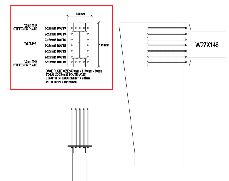
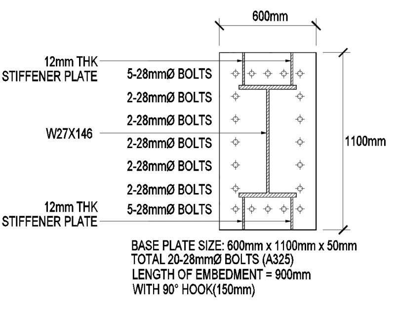
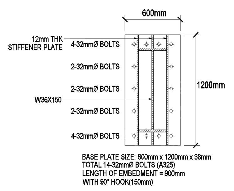
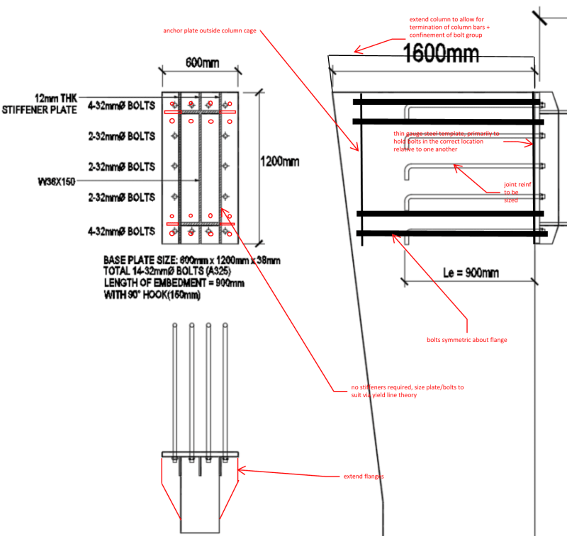
Overall it still looks wrong to me I'm afraid. For example you still have bolts on only one side of the flange, you still have these bent bolts providing the anchorage, you have the bolts virtually hard against the stiffeners (can they even be tightened?) (you'll just overload the weld locally, especially critical if it's intended to be a fillet weld), no information on welding is given at all (has it been reviewed/designed yet?), no depth/width of stiffeners is given (the full depth one looks suspect, does it work for the loads imposed from the bolts acting as a beam?), there is limited connection of full depth stiffener to the side of the flange (two fillet welds presumably to take a large proportion of the loads in probably 2-3 bolts), still have square layout of bolts which was mentioned as not being desirable, etc. How do you plan on ensuring the bolts are placed within tolerance within the concrete? Does the bearing on the concrete even work (under the compression flange)?
Edit - As people have noted, the concrete side of the connection will no doubt limit the connections capacity, and nothing has been provided in this regard.
This is more what I was thinking if I was presented with the same problem (of course I have no idea what the loads actually are), maybe other agree/disagree in terms of it being a more standard simplified/well experienced/tested approach? I'd design the end plate to the requirements of
SCI398 as thats pretty much the state of the art method for this type of thing.