Continue to Site

Eng-Tips is the largest engineering community on the Internet

Intelligent Work Forums for Engineering Professionals

  • Congratulations JAE on being selected by the Eng-Tips community for having the most helpful posts in the forums last week. Way to Go!

Shear flow for indeterminate beam

StrEng007

Structural
Aug 22, 2014
546
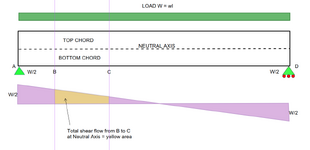
I got a question that's come up regarding the theory behind how shear flow works. Considering a simple span beam with uniform loading. I've always used the following to explain shear flow.
The chord force of the beam is the area under the shear flow diagram. Said in a different way, shear flow is the accumulation of shear stress that results in the chord force due to moment.

Equations:
V = wL/2
M= wL²/8
Shear Flow = VQ/I
Chord force in the beam section = the area under the shear flow diagram = (VQ/I) x L/4

Putting some numbers behind it. Take a 8"x12" rectangular cross section:
I = 1152 in^4
Q = 144 in^3

w = 100 lb/ft, L= 10ft
M = 1250 lb-ft or 15,000 lb-in
V = 500 lb

Chord force illustrated by shear flow:
Shear Flow = 62.5 lb/in
Chord Force = 62.5 lb/in x (120 in/4) = 1,875 lb

Chord force illustrated by bending stress:
Bending Stress = 15,000 lb-in (6 in)/ 1152 in^4 = 78.125 psi
Chord Force = 78.125 psi x (8in)(6in)x1/2 = 1,875 lb

However, this theory doesn't work when applied to a single span beam with fixed end conditions. The shear at the end of this beam would be the same as the simple span beam shown above. However, we know that using the area under this shear flow diagram would NOT be equal to the maximum chord force produced by the moment.

So the question is, when you have a fixed end single span beam, is shear flow calculated in the same exact manner? If so, how do you explain how to derive the chord forces in relationship to the shear flow force?
 
Replies continue below

Recommended for you

So the question is, when you have a fixed end single span beam, is shear flow calculated in the same exact manner?

Yes in the sense that VQ/It will still produce an appropriate result.

If so, how do you explain how to derive the chord forces in relationship to the shear flow force?
It requires adding a bit of nuance to your initial procedure to make it more general in nature.

The CHANGE in chord force of the beam is the area under the shear flow diagram. THE MAGNITUDE OF CHORD FORCE AT ANY LOCATION IS THIS CHANGE ADDDED TO THE STARTING VALUE AT THE SUPPORTS WHICH, IN THE CASE OF NON-SIMPLE SPAN BEAMS, MAY WELL BE NON-ZERO.

I suspect that the main thing that you are missing is giving proper account of the chord forces present at the end of your fixed ended beam.
 
THE MAGNITUDE OF CHORD FORCE AT ANY LOCATION IS THIS CHANGE ADDDED TO THE STARTING VALUE AT THE SUPPORTS WHICH, IN THE CASE OF NON-SIMPLE SPAN BEAMS, MAY WELL BE NON-ZERO.

Oh, yes that makes a lot of sense. Hence the reason why the overall magnitude of moment is always WL²/8. It just happens that with fixed ends, some negative moment is pulled out of that overall magnitude (i.e. wl²/12 + wl²/24 = wl²/8).

So going back to what you said, let's say I made a built up steel beam from two separate identical square shapes. Regardless of the beam being fixed or simple span, to get the composite action all I need to do is design the weld between the two beams using the shear flow VQ/I. It doesn't matter that the beam's ends "start" with an internal moment?
 
It doesn't matter that the beam's ends "start" with an internal moment?

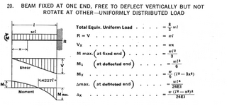
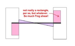
That's right. Again, for theoretical nuance, we'll acknowledge that the beam fixity that produces the starting chord forces implies a great deal of shear flow. It's just shear flow that occurs outside of the span being studied. Consider the shear diagram on an encastre version of such a beam.

c01.JPG
 
I think I might include that drawing on the next set of calculations I submit and see whether the building surveyor reacts. I especially love the description "So much f'ing shear!".

(They probably won't, down here nobody even looks at the calculations submitted. Oddly enough the only times I am even asked for them is for domestic jobs. I can and do design sprawling industrial plants and never get asked for anything more than a signature.)
 
I think you're mixing things up.

in a beam with a uniform load, shear is constantly, linearly, increasing (due to the distributed load), the moment is increasing parabolically.
the local section shear (VQ/I) is proportional to the local shear which of course includes the end reaction support force.

I would rather say that the shear in the beam is the area under the distributed load - the end reaction.
 
I got a question that's come up regarding the theory behind how shear flow works. Considering a simple span beam with uniform loading. I've always used the following to explain shear flow.
The chord force of the beam is the area under the shear flow diagram. Said in a different way, shear flow is the accumulation of shear stress that results in the chord force due to moment.

Equations:
V = wL/2
M= wL²/8
Shear Flow = VQ/I
Chord force in the beam section = the area under the shear flow diagram = (VQ/I) x L/4

Putting some numbers behind it. Take a 8"x12" rectangular cross section:
I = 1152 in^4
Q = 144 in^3

w = 100 lb/ft, L= 10ft
M = 1250 lb-ft or 15,000 lb-in
V = 500 lb

Chord force illustrated by shear flow:
Shear Flow = 62.5 lb/in
Chord Force = 62.5 lb/in x (120 in/4) = 1,875 lb

Chord force illustrated by bending stress:
Bending Stress = 15,000 lb-in (6 in)/ 1152 in^4 = 78.125 psi
Chord Force = 78.125 psi x (8in)(6in)x1/2 = 1,875 lb

However, this theory doesn't work when applied to a single span beam with fixed end conditions. The shear at the end of this beam would be the same as the simple span beam shown above. However, we know that using the area under this shear flow diagram would NOT be equal to the maximum chord force produced by the moment.

So the question is, when you have a fixed end single span beam, is shear flow calculated in the same exact manner? If so, how do you explain how to derive the chord forces in relationship to the shear flow force?
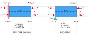
Shear flow is calculated in exactly the same manner for a simple and fixed beam. In both beams, the shear flow is zero at midspan and maximum at supports. In the simple beam, top fibers are compressed throughout the span, whereas in the fixed beam, top fibers near midspan are compressed while fibers near each support are stretched. The change in axial force in the top (or bottom) fibers from support to midspan is equal for a fixed and simple beam. In either case, the difference in moment between support and midspan is wl^2/8.
 
Last edited:
Shear flow is calculated in exactly the same manner for a simple and fixed beam. In both beams, the shear flow is zero at midspan and maximum at supports. In the simple beam, top fibers are compressed throughout the span, whereas in the fixed beam, top fibers near midspan are compressed while fibers near each support are stretched. The change in axial force in the top (or bottom) fibers from support to midspan is equal for a fixed and simple beam. In either case, the difference in moment between support and midspan is wl^2/8.
The sketch below illustrates that the horizontal shear is the same whether the beam is fixed or simply supported.
1749677620013.png
 
Seems like I'm talking to myself. Perhaps the OP has passed on. If so, RIP, OP.
 
BAretired,
Sorry for the delay. I like your sketch, it adds another perspective and makes sense.

For the fixed end beam, why are the F values at the top side pointing the same direction? As you mentioned, isn't the midspan fiber in compression, and the end in tension?
 
BAretired,
Sorry for the delay. I like your sketch, it adds another perspective and makes sense.

For the fixed end beam, why are the F values at the top side pointing the same direction? As you mentioned, isn't the midspan fiber in compression, and the end in tension?
I think the F's in his sketches are the ones taken in the slice just before midspan, and the ones just after midspan would flip direction.
 
BAretired,
Sorry for the delay. I like your sketch, it adds another perspective and makes sense.

For the fixed end beam, why are the F values at the top side pointing the same direction? As you mentioned, isn't the midspan fiber in compression, and the end in tension?
F and F' are pointing in the same direction because it is a free body diagram of a beam cut at midspan. Fixity at the support and positive moment at midspan requires F and F' to both point left for top fibers and right for bottom fibers. The horizontal shear to be transferred at the neutral axis is the sum of those two forces. See also EngDM's post directly above this.
 
F and F' are pointing in the same direction because it is a free body diagram of a beam cut at midspan. Fixity at the support and positive moment at midspan requires F and F' to both point left for top fibers and right for bottom fibers. The horizontal shear to be transferred at the neutral axis is the sum of those two forces. See also EngDM's post directly above this.
This brings up an interesting thought in my head. When bracing a cantilever beam going into negative bending at the support (to decrease Lu) we typically size it for 2% of the factored compressive load at the brace point, which we have been determining as negative moment / depth of beam. If F and F' get added together as shown in your diagram above, does this mean for a cantilever beam compressive flange brace you need to determine that load as (max positive + max negative) / depth of beam? That's one thing that is confusing me with your sketch @BAretired, when you go from negative bending at the support to positive bending, your compressive flange flips, so wouldn't the sign of F and F' be different?
 
This brings up an interesting thought in my head. When bracing a cantilever beam going into negative bending at the support (to decrease Lu) we typically size it for 2% of the factored compressive load at the brace point, which we have been determining as negative moment / depth of beam. If F and F' get added together as shown in your diagram above, does this mean for a cantilever beam compressive flange brace you need to determine that load as (max positive + max negative) / depth of beam? That's one thing that is confusing me with your sketch @BAretired, when you go from negative bending at the support to positive bending, your compressive flange flips, so wouldn't the sign of F and F' be different?
The 2% comment in red is a different matter entirely. The topic in this thread is "Shear flow for indeterminate beam".

Shear flow is calculated by the formula VQ/I, or if shear stress is required it is VQ/It. That formula is correct for any beam whether cantilever, simple or continuous. Shear flow for a beam segment is proportional to the difference in bending moment from end to end of segment. If one end has -M and the other has +M, the difference is 2M and the shear flow over the length of the segment is equal to 2M/d where d is the effective moment arm. So F and F' are both pointing in the same direction for cantilevers.
Yes I know this thread is for shear flow, however OP has described the chord force as the shear flow. Lateral bracing requires bracing 2% of the compression chord force. So my original question is in relation to that.
 
We ARE talking about chord force. We are NOT talking about lateral bracing.

The top chord force is equal and opposite to the bottom chord force. For a rectangular beam, the total horizontal shear force between the two chords, i.e. at the neutral axis, is equal to the chord force in each chord.

1750378787713.png
 
Last edited:
In the diagram below, M1 is a positive moment and Mmax is a negative moment. If F1 and Fmax are M1/c and Fmax/c respectively where c is the moment arm, they both point right for top fibers and left for bottom fibers. The horizontal shear at the neutral axis is equal to the top or bottom chord force, namely F1+Fmax.
1750433037061.png
 
We ARE talking about chord force. We are NOT talking about lateral bracing.

The top chord force is equal and opposite to the bottom chord force. For a rectangular beam, the total horizontal shear force between the two chords, i.e. at the neutral axis, is equal to the chord force in each chord.

View attachment 11009
I had a thought that ran parallel to the current discussion. I understand that OP is not talking about bracing. I had a question regarding chord force to further my understanding, in relation to chord force and lateral bracing requirements...
 
In the diagram below, M1 is a positive moment and Mmax is a negative moment. If F1 and Fmax are M1/c and Fmax/c respectively where c is the moment arm, they both point right for top fibers and left for bottom fibers. The horizontal shear at the neutral axis is equal to the top or bottom chord force, namely F1+Fmax.
View attachment 11025
So to clarify, if you wanted the compression chord force at the RHS, you would take Mmax/c and NOT the sum of M1/c + Mmax/c. In your sketch above on June 11th you have F + F' = chord force, but the moment due to F is postive and F' is negative, so their top chord loads are in opposite directions (one tension one compression) so why are they additive?
 
So to clarify, if you wanted the compression chord force at the RHS, you would take Mmax/c and NOT the sum of M1/c + Mmax/c. In your sketch above on June 11th you have F + F' = chord force, but the moment due to F is postive and F' is negative, so their top chord loads are in opposite directions (one tension one compression) so why are they additive?
M1 is positive and Mmax is negative by convention but they are both clockwise moments. F1 pushes the top chord to the right. Fmax pulls the top chord to the right. That is why F1 and Fmax are additive. Together, they represent the total axial force in the top chord. A free body diagram of the top chord would show three forces, F1 at left, Fmax at right and horizontal shear at the neutral axis over the full length, all three forces adding to zero for equilibrium.

Axial force varies along the length of beam, F1 at left end, Fmax at right end, but the total axial force acting on the top chord is F1+Fmax. That is the force which must be resisted by horizontal shear at the N.A.
 

Part and Inventory Search

Sponsor