Continue to Site

Eng-Tips is the largest engineering community on the Internet

Intelligent Work Forums for Engineering Professionals

  • Congratulations IRstuff on being selected by the Eng-Tips community for having the most helpful posts in the forums last week. Way to Go!

Cutout in lower wing skin: How can I hand calc this?

Ab1869

Aerospace
May 23, 2025
2
Hello,

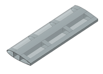
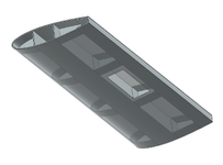
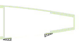
Let's say I have this composite wing structure: center box spar, aft spar, ribs and a upper/lower wing skin all bonded together. I want to make a rectangular cutout on the lower wing skin and either show this is good or size an externally bonded "donut" doubler around the cutout, all via hand calcs.

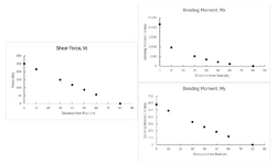
I used Example A5.12 in Bruhn to generate the attached shear force and bending moment diagrams about different stations of the wing (Mx is about the chord and My is about the spanwise axis of the wing). These are resolved about an axis 40% of the chord. From here, I'm not sure how to proceed.

I'd assume the skin in this area would be experiencing some combined loading: in-plane tension due to bending, as well as some shear due to torsion.

Would I go to A15 in Bruhn (shear flow in closed-thin walled section) and analyze the stresses prior to the cutout in this cell? But once I introduce the cutout, it's no longer a closed-section right? How would I compare the pristine to the cutout cell? Or is this a plates/shells problem?

This is all theoretical and none of this is going to fly. I'm just working on this out of personal curiosity and possibly a project to show on a portfolio. I went to school for mechanical engineering so roleplaying as an aero engineer here. I appreciate any guidance you could provide!
 

Attachments

  • Wing Upper Transparent.png
    Wing Upper Transparent.png
    136.2 KB · Views: 10
  • Lower with Cutout.png
    Lower with Cutout.png
    112.2 KB · Views: 11
  • Wing Cross-Section.png
    Wing Cross-Section.png
    17 KB · Views: 9
  • Combined Wing Plots.png
    Combined Wing Plots.png
    72 KB · Views: 8
Replies continue below

Recommended for you

I'm sure a repair could be designed, but it would be extensive to analyze, and I doubt a hand calc could do it ...not without massive assumptions.

1st, what are the ply orientations and lay-up of the wing skin ?

2nd, what are the original loads, even the internal loads for a couple bays around this cut-out (which may be easier to get (or to use) than the external loads on the wing ?

3rd, your doubler orientations and lay-up ? I would have something like 3x the size of the cut-out (length and breadth) tapering plies to the edges. I would have an internal doubler and the cut-out cover would attach to this (smooth OML).

4th, wet wing ?

5th, you could design the cut-out cover to be effective (quite hard to do) and that would minimise the doubler (to a local splice). Recognise I don't know why you're doing this, what you're trying to achieve with the cut-out ...

6th, DTA ??

7th, that's just a start !!
 
wing torsional stiffness would be severely impacted, as the aft cell is no longer a closed cell for this bay. this would affect aeroelastic characteristics of the wing involving the torsional mode (divergence, ctrl reversal, flutter analyses need to be revisited).

Torque in this bay would be carried by the forward cell, and differential bending of the forward cell and aft spar. So the forward cell and aft spar margins of saftey would need to be recalculated for the revised internal loads.

The external doubler would never restore the original strength and stiffness margins, and any significant external doubler is not likely to make the aerodynamicists happy.
 
I've done the certification of a wing skin cutout on a composite aircraft. Granted, only once.
I did it with "hand-calcs" (if you want to call it that) and test, in combination.
Note that the solution must include tests if it won't have enough data from analysis alone. I admitted that without FEA the data would be too sparse to be certain that the entire stress picture could be understood. Instead I worked up a detailed load set and applied them to the wing, before and after. That and the writing of the test procedure took several days (simple light aircraft). The test set up took several days, and the test itself less than a day. Can anyone say that about setting up a FEM in under a week??

"This is all theoretical and none of this is going to fly."

Well then you're not going to do a test.
 
I've done the certification of a wing skin cutout on a composite aircraft. Granted, only once.
I did it with "hand-calcs" (if you want to call it that) and test, in combination.
Note that the solution must include tests if it won't have enough data from analysis alone. I admitted that without FEA the data would be too sparse to be certain that the entire stress picture could be understood. Instead I worked up a detailed load set and applied them to the wing, before and after. That and the writing of the test procedure took several days (simple light aircraft). The test set up took several days, and the test itself less than a day. Can anyone say that about setting up a FEM in under a week??


Well then you're not going to do a test.

I would love to pick your brain, mind sharing your general hand calc approach to signing off on the cutout (of course, in your case, testing was a big part of this).
 
Sorry, I don't do consulting any more. And way too busy to do it on the side, now.
 
I want to make a rectangular cutout on the lower wing skin and either show this is good or size an externally bonded "donut" doubler around the cutout
why? even if the wing box is not a fuel tank, no one in their right mind is going to fly an airplane with a giant hole in the main wing box.

any such damage is going to need a structural repair to restore the skin stiffness and strength.

if this is just some theoretical exercise, then
- do you know how to analyze the wing box (a 3 cell box) without the cutout? per classical methods in Bruhn or Peery or Flabel?
- you are going to have to assume some wing loading
- once you get load distributions, check strength and buckling in all sections
- then with a giant hole, you remove the skin area, and recalculate the axial loads due to applied moments, and the shear flows due to applied shear and torsion
- then recheck buckling in all remaining sections
- and apply a conservative Kt to the hole in the skin, and recheck strength in all remaining sections.
- and so on.

we won't even go into the significant complications of checking the skin to spar joints, either bolted or bonded.
 

Part and Inventory Search

Sponsor