Navigation
Install the app
How to install the app on iOS
Follow along with the video below to see how to install our site as a web app on your home screen.
Note: This feature may not be available in some browsers.
More options
Style variation
-
Congratulations dmapguru on being selected by the Eng-Tips community for having the most helpful posts in the forums last week. Way to Go!
You are using an out of date browser. It may not display this or other websites correctly.
You should upgrade or use an alternative browser.
You should upgrade or use an alternative browser.
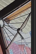
For fun, how would you analyze this joist?
- Thread starter ANE91
- Start date
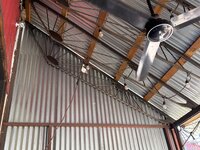
I would let AI analyze it, since it looks like AI invented it. If anything screams "FEA", it is this. Looks like a hand-calc nightmare. The uphill side looks like a real conservative designed it while the downhill side looks a little LSD may have been involved.
Is that a single angle top chord? Is the bottom chord a single solid round? I think the wall panel reflection on the end joist makes it look like 2 thin bars with something intermittently welded between them.
I would bet it was tested for strength more than designed.
Is that a single angle top chord? Is the bottom chord a single solid round? I think the wall panel reflection on the end joist makes it look like 2 thin bars with something intermittently welded between them.
I would bet it was tested for strength more than designed.
TRAK.Structural
Structural
"OK BY INSPECTION"
Just kidding, but this does look like a fairly short span. My guess is this thing was designed/fabricated by an artist. If so, I'd have a hard time justifying any type of calcs for something that had no QA/QC involved in the fabrication.
Just kidding, but this does look like a fairly short span. My guess is this thing was designed/fabricated by an artist. If so, I'd have a hard time justifying any type of calcs for something that had no QA/QC involved in the fabrication.
I assume that you mean the circular part with three attached "legs". I don't think an analysis has to be very complicated but it depends on the loading and if the circular part is supported upwards.
There is something going upwards above the circle, can that be a support? If it is and the loading is the same in the three legs, and the circle has a reasonable stiffness, and the dome in the circle has no structural function. Then it shouldn't be to complicated.
But if the circle and the dome in the middle is working as a unit made of "thin" plate, that would be different.
I would use FEM to see how it performs when loaded.
Where did you find it ?
?
There is something going upwards above the circle, can that be a support? If it is and the loading is the same in the three legs, and the circle has a reasonable stiffness, and the dome in the circle has no structural function. Then it shouldn't be to complicated.
But if the circle and the dome in the middle is working as a unit made of "thin" plate, that would be different.
I would use FEM to see how it performs when loaded.
Where did you find it
Now you have me lost. Where is there a circular part with 3 legs and a something going upwards?I assume that you mean the circular part with three attached "legs". I don't think an analysis has to be very complicated but it depends on the loading and if the circular part is supported upwards.
There is something going upwards above the circle, can that be a support? If it is and the loading is the same in the three legs, and the circle has a reasonable stiffness, and the dome in the circle has no structural function. Then it shouldn't be to complicated.
I am probably the one who got lostNow you have me lost. Where is there a circular part with 3 legs and a something going upwards?
The subject is probably the weird locking trusses.
It's strange what we notice.I am probably the one who got lost. The thing that caught my eye is at the upper right corner of the picture.
I didn't even see the fan until I went back for the third time, looking for a circle with a dome in the middle, and then there it was.
Four eyes is better than twoIt's strange what we notice.
I didn't even see the fan until I went back for the third time, looking for a circle with a dome in the middle, and then there it was.
I will make another try, hopefully more on the intended subject
I have actually studied something similar a few years back, then it was however much larger. What I don't see in the picture is anything stabilizing the "truss" bottom chord out-of-plane. But the question was how I would analyze it.
I would use FEM and model it with beam 1D elements and plate elements 2D where appropriate. Then I would do a linear static analysis, to see what happens. Buckling analysis will hopefully show how sensitive it is, out-of-plane. Then I would use non-linear analysis, my experience is that this can be sensitive to deformations and imperfections.
I noticed this years ago when an Architect and I would go into an existing building and look around for whatever info we each needed. On the ride back to the office, you would think we were not in the same building 20 minutes earlier. Each one only noticed and mentally retained what pertained to their field and very little else.It's strange what we notice.
For example, I noticed the porch columns were rotted out at the bottom but had an interior solid square column center that was not rotted. I did not notice what style they were. He noticed they needed painting and would have looked better if they had been Corinthian style rather than Doric but never noticed the rot nor the interior structural column.
Greenalleycat
Structural
That thing is awesome, I want one in my house
If I was actually analysing it, I don't think it would be too hard to rough it out
Looks like all the rods are aimed at a common node (for each junction) so I'd model it on that basis
Ignore the gusset and check those separately by hand at the end
It is probably fine for the low-demand situation it's in so I'd be expecting it to calc out OK
I'd be nervous if it was carrying significant weight though - I don't think you could get a realistic capacity for a thing like that from analysis to know that 'close to the line' was going to work
Not a constant depth. Top chord looks like eccentrically loaded single angle with Gravity Loads probably going down vertical leg but wind load picking up midway across horizontal leg. My idea of a hand calc set sail at not a constant depth. I do think it is lightly load in the field, not lightly load per design standards. By "lightly loaded", I mean the small lights hung from it by the Master Electrician. Not many use "orange conduit cord" anymore.
On the other hand, the component size is on par with the "massive wall framing". I think the wall framing is angle, not tube. Hopefully this is just a storage lean to.
On the other hand, the component size is on par with the "massive wall framing". I think the wall framing is angle, not tube. Hopefully this is just a storage lean to.
Easy... I'd use 0.9 x depth to determine the As required for the moment to calculate the area of the top chord and use 0.9 x this to determine the As for the bottom chord. I'd calculate the shear and calculate the tension/compression in the greatest slope diagonal and calculate the area of the BAR that will withstand this load. I'd then plug this into a frame or FEM program to confirm the sizes.
- Thread starter
- #16
@Ron247 chords looked like square tubing.
@ThomasH nifty lil breakfast spot. House converted into a restaurant.
@sdz not a bad idea!
I doubt this thing saw any design or QA/QC. Not too worried about it; it’s stood long enough. Most offensive parts to me are the tack welds at bar ends and the rightmost fan that someone else pointed out.
@ThomasH nifty lil breakfast spot. House converted into a restaurant.
@sdz not a bad idea!
I doubt this thing saw any design or QA/QC. Not too worried about it; it’s stood long enough. Most offensive parts to me are the tack welds at bar ends and the rightmost fan that someone else pointed out.
LittleInch
Petroleum
- Thread starter
- #18
That’s a plastic planter, but you can’t tell without having been there. Impressive eye for detail nonetheless.
Similar threads
- Question
- Replies
- 3
- Views
- 2K
- Question
- Replies
- 23
- Views
- 7K
- Question
- Replies
- 18
- Views
- 7K
- Replies
- 17
- Views
- 4K


