Hi BA,
Appreciate your help.
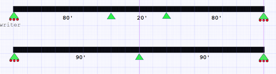
1- How would you configure a box truss to simulate a roller support in this image:
A column hinged top and bottom simulates a roller support. That is not the issue and the architect has already approved that.
The architect has also approved a cross braced structure at midspan, but you are not content with that.
If you object to the diagonal braces, perhaps you would prefer a rigid frame adequate to resist horizontal forces parallel to the bridge. If so, problem solved.
My main concern is with seismic forces. I have no idea where this structure is situated, but we know that there has been a recent earthquake in Turkey, so be prepared to address that issue.
Interesting video...Maybe we should go for a cable stayed bridge...
(just joking)
The span is 27.75 m. How much pinned supports would you consider in an analytical model for this truss? One at each end or two at each end?
Hard to say what is intended here. The trusses are not symmetrical; on the right side there's no end diagonal, the top chord extends to an end vertical member which appears to align with the exterior of the supporting box truss. My guess is that it is intended to simulate a pin on the left and a roller on the right to permit temperature strain to occur easily, but it is an unusual detail. That would suggest two each truss top and bottom on the left. It is not clearly a roller on the right, but perhaps one top and two bottom each truss. I am tempted to say for the right end, one pin top and one pin bottom for each truss, but that leaves two legs of the box truss unattached. Let's just say it seems like a strange detail.
Others may see something that I missed in the photo; if so please contribute your thoughts.