Eng-Tips is the largest forum for Engineering Professionals on the Internet.

Members share and learn making Eng-Tips Forums the best source of engineering information on the Internet!

  • Congratulations dmapguru on being selected by the Eng-Tips community for having the most helpful posts in the forums last week. Way to Go!

Replace partition wall under roof joist with beam

magicming

Civil/Environmental
Joined
May 1, 2021
Messages
23
Location
CA
Hi there,

It is my first time to check roof joists and not sure if I am right, please give me some advise.

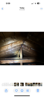
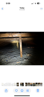
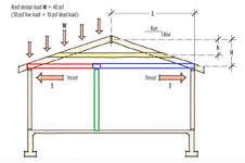
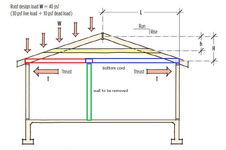
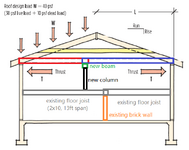
I have a client asking me the recommendation to replace a section of partition wall (2x4 studs, 16" o.c.) under the roof joists by using beam to support the roof joists (bottom cord of the roof truss structure). The roof joists (2x6, 16" o.c.) were not one piece spanning from perimeter wall to perimeter wall. They are two pieces attached together side by side (about 1.5ft overlapping) and supported by the partition wall close to the middle of the span. The partition wall sits on floor joist, not a beam. Also, there was no load bearing wall under this partition wall. For the roof truss, see attached pictures, they are simple triangle roof truss. Rafter 2x5, 16" o.c., colar tie 2x4, 32" o.c., bottom cord/roof joist 2x6, 16" o.c. My analysis is that the roof joist/bottom cord mainly under tension. So the partition wall just simply supports the roof joists from falling. In this case, how much load I should design for the beam? is 15psf dead load + 5psf live load enough? Am I correct for the roof joist analysis? Please give me some help. Thanks.
 

Attachments

  • IMG_8653.PNG
    IMG_8653.PNG
    207.4 KB · Views: 37
  • IMG_8654.PNG
    IMG_8654.PNG
    141.8 KB · Views: 37
  • IMG_8655.PNG
    IMG_8655.PNG
    142.4 KB · Views: 37
1) You may want to provide the actual pictures and not screenshots from your phone.

2) It looks like roof rafters with the occasional collar tie to resist the horizontal thrust. See link for explanation of how they work together: https://www.jlconline.com/how-to/framing/rafter-ties-and-shallow-pitch-roofs_o

The amount of thrust on those collar ties will vary greatly based on roof pitch, snow loads, are they connected adequately to the roof rafters, etc.
Thanks for your reply, Bear. One picture is from video screenshot, the other two are from actual pictures. As seen in the attached picture, the collar ties are doubly spaced as the rafter. I believe they are resisting horizontal thrust but the main resistance is from the fastened bottom cords (red and blue boxes) as they are same spaced with the rafter. So for the partition wall (green box), it shouldn't resist any vertical loads by snow or whatever. That's why I am asking just consider the basic dead load 15 psf and another 5psf for potential future maintenance. Do you think it is reasonable? Thx
 

Attachments

  • Capture.PNG
    Capture.PNG
    218.2 KB · Views: 9
Can we call them "rafters" instead of "roof rafters" and "roof joists". One of my pet peeves.
 
rafter - roof rafter, shingles are nailed to the sheathing that's nailed to the rafter,

joist - -- ceiling joist - insulation sits on it and maybe a vapor barrier and the gypsum board.

Generally the shallower the roof, the more thrust you get and need to resist. This kind of construction typically will not "math out." I've had this issue several times on houses before the 1960s. Once trusses took over this tended to go away.

Usually the rafter collar ties (which are not actually considered to take any tension, they are there to keep the ridge board and the rafters together in wind uplift) are undersized, usually the rafters are undersized, and for the span, commonly one lacks the purlins and purlin braces that larger spans need.

when the ceiling joist is elevated, one tends to hear them referred to as rafter ties or raised rafters.

At any rate, the math is not friendly and the space for the connections is also not favorable.

Roof live load would commonly be 20 psf, not 5 psf.

I think there's an FAQ over in the wood forum.

that also links to several archived threads that go into a lot of the modeling rabbit holes.
 
Last edited:
rafter - roof rafter, shingles are nailed to the sheathing that's nailed to the rafter,

joist - -- ceiling joist - insulation sits on it and maybe a vapor barrier and the gypsum board.
ChatGPT?
 
Your rafters and ceiling joists appear to both be 16" on center. That somewhat tells me you are in a snow area or your span exceeds 2x6 at 24" oc. What is being called a collar tie is 32" on center and I assume "double spaced" means 2 rafter spaces or 32"? If so, it most likely was not intended to resist thrust since every rafter does not have one. It is a collar tie that is typically supposed to be in the upper third of the rafter and typically a maximum of 4' on center. Because a lot of roof framing is 24" on center, carpenters began saying "every other rafter" when it is still 4' on center in most codes. That would be every third rafter at 16" oc. Tension ties on the other hand, are generally in the lower third and present on every rafter generally.

Most roof dead loads are 10 psf because shingles alone are 3 psf generally, +decking at 2 psf + framing + ceiling covering, etc.. If you have a tile or some heavier roof, it goes up from there. The minimum Roof Live Load is at least 20 psf and goes up from there for snow.

What is the vertical 2x4 in your picture? What spacing and what does it attach to?

Generally, most of the ceiling joist (CJ) attachment is to the wall and not to each other. Be cautious if you remove the wall, you may need to attach the CJs to each other first due to the thrust.

Also don't call them trusses, like XR250, that is one my pet peeves, they are triangular, but not trusses. That is referred to as "stick-built". I assume there is a ridge board at the peak.

The easy part is sizing the beam, the harder parts are routing the post loads at each end of the new beam somewhere, dealing with the new deflection from the beam and if the wall is longer than 16', dealing with joints in a wood beam if you are planning on a wood dimension lumber beam.
 
Last edited:
rafter - roof rafter, shingles are nailed to the sheathing that's nailed to the rafter,

joist - -- ceiling joist - insulation sits on it and maybe a vapor barrier and the gypsum board.

Generally the shallower the roof, the more thrust you get and need to resist. This kind of construction typically will not "math out." I've had this issue several times on houses before the 1960s. Once trusses took over this tended to go away.

Usually the rafter collar ties (which are not actually considered to take any tension, they are there to keep the ridge board and the rafters together in wind uplift) are undersized, usually the rafters are undersized, and for the span, commonly one lacks the purlins and purlin braces that larger spans need.

when the ceiling joist is elevated, one tends to hear them referred to as rafter ties or raised rafters.

At any rate, the math is not friendly and the space for the connections is also not favorable.

Roof live load would commonly be 20 psf, not 5 psf.

I think there's an FAQ over in the wood forum.

that also links to several archived threads that go into a lot of the modeling rabbit holes.
Thanks for your reply, Lexpatrie. This is a very old house, maybe built before 1950s. For the rafter, I believe there will be more live load. In Toronto there is more than 20 psf live load. But for the bottom cord, as it doesn't have vertical forces transfer from the rafters (only horizontal forces in tension I believe), is it still need to design 20psf LL? If that is the case the beam will be fairly big, just don't want to overdesign it too much.
 
It's just as easy to attach the actual photo as it is to attach the screenshot of the gallery on your phone and is much better definition.

The issue is really how much load can be sensibly seen by the ceiling joists. Currently they have the plasterboard plus some rather skimpy looking insulation, but if the owner decided to put some boards and start storing stuff? or even just inspecting the inside of the roof??

How long is that structure? Beam deflection is going to be a concern and if anything gets loaded up there you could easily have a sagging ceiling.

What is the current or plan for tying the ceiling joist together?
Do you plan on simply replacing the wall with a beam in the same position , i.e. off centre?

This could very easily end up being a lot more complex than it might seem given this 75 year old building design looks very questionable to modern standards. Probably all OK whilst nothing changes, but as soon as it all sorts of things will start moving and possibly breaking.
 
Last edited:
But for the bottom cord, as it doesn't have vertical forces transfer from the rafters (only horizontal forces in tension I believe), is it still need to design 20psf LL? I
You need to determine how that vertical 2x4 fits into the puzzle. It does not matter why someone installed it. It is there. Physics determines what it will do, not what some carpenter intended. It may have been a temporary ridge board support, I doubt that, but in any case, they left it in place.

The new beam will sag some. That makes the CJS go down some. The attachment of the vertical 2x4 periodically will try to resist that downward movement. Also, rafter load can make the ridge want to go down some, the vertical stiffleg struts that to the CJs.
 
Your rafters and ceiling joists appear to both be 16" on center. That somewhat tells me you are in a snow area or your span exceeds 2x6 at 24" oc. What is being called a collar tie is 32" on center and I assume "double spaced" means 2 rafter spaces or 32"? If so, it most likely was not intended to resist thrust since every rafter does not have one. It is a collar tie that is typically supposed to be in the upper third of the rafter and typically a maximum of 4' on center. Because a lot of roof framing is 24" on center, carpenters began saying "every other rafter" when it is still 4' on center in most codes. That would be every third rafter at 16" oc. Tension ties on the other hand, are generally in the lower third and present on every rafter generally.

Most roof dead loads are 10 psf because shingles alone are 3 psf generally, +decking at 2 psf + framing + ceiling covering, etc.. If you have a tile or some heavier roof, it goes up from there. The minimum Roof Live Load is at least 20 psf and goes up from there for snow.

What is the vertical 2x4 in your picture? What spacing and what does it attach to?

Generally, most of the ceiling joist (CJ) attachment is to the wall and not to each other. Be cautious if you remove the wall, you may need to attach the CJs to each other first due to the thrust.

Also don't call them trusses, like XR250, that is one my pet peeves, they are triangular, but not trusses. That is referred to as "stick-built". I assume there is a ridge board at the peak.

The easy part is sizing the beam, the harder parts are routing the post loads at each end of the new beam somewhere, dealing with the new deflection from the beam and if the wall is longer than 16', dealing with joints in a wood beam if you are planning on a wood dimension lumber beam.
Thanks for your detailed reply, Ron247. The roof span is 24'. Rafters are 2x6 and 16" oc. A ridge beam is at the top. Collar ties (technically not, as they are installed at the lower side of the rafters, about 4' from the bottom) are 2x4, 32" oc. Vertical 2x4s are spaced about 9.5' and connecting the ridge beam and bottom cords. Bottom cords are 2x6, 16" oc, and they are not one piece as shown in the attached picture (one 11' and the other 13'). they are spliced and attached together by nails. A partition wall is underneath to support them.

I agree with you that these are not typical trusses, simply trianglar. Also I agree that there are more loads on the roof considering dead load, live load, and snow loads. Since these are supported by the roof structure and my analysis tells me that they are not supported by the partition wall. It looks to me the partition wall simply support the bottom cords from falling and reduce deflection due to the long span (as I don't think a one piece 2x6 spanning 24' could meet the deflection as per the building code).

My plan is to remove the partition wall section my client want s to remove, and use a beam to support the bottom cords.
 

Attachments

  • Capture.PNG
    Capture.PNG
    220.2 KB · Views: 2
How long is your opening going to be? When your new post/point load comes down to the floor below, how are you dealing with that? Do you know which direction, size and spacing the floor joists are?

The ties that are 32" oc, are taking some thrust, because they are there, not because they were intended to. No need for lower ties if the CJs are present. Collar ties in the upper third are for wind uplift, not gravity loads and thrust. Even they will take some thrust, again, just because they are there. Sounds like the vertical 2x4s were intended to be temporary ridge board braces. I hate it when they leave temp stuff, because I know it provides a potential load path that could have been avoided. Really old houses used to be built with no ridge board, the rafters just butted into each other so there was no ridge board to temporarily support.

Most codes specify the CJ design load as 10 psf to 20 psf unless you floor for storage, then it is 30 psf. Not sure about which code applies in your area. Probably the 20 psf but you need to confirm.
Hi Ron247, good to receive your reply. It is a regular old detached one-storey house, so I think 20 psf should be enough. The house is at Toronto. We have Ontario Building Code, but very similar to National Building Code of Canada that is similar to code in the states.

I agree the upper ties are not the main player to resist thrust, the ceiling joists are. The temporary ridge board braces also confused me at the beginning.

The new beam span is 11'6". The beam will be supported by two wood columns. There is no walls (neither load bearing nor non-load bearing) right underneath the beam location, so I couldn't extend these two columns direct to the basement with a footing. Another reason is that the owner don't want columns messing his plan for the basement. So I am planning to put two beams under these two columns to transfer the loads to the adjacent load bearing wall and perimeter wall (both are brick walls). The first floor joist is 2x10, and the span is 13 ft .

My plan for the new beam (green color in picture) replacing the partition wall is 2-2x8 LVL. The floor height is 8ft, if deeper than 8" then the beam will affect the appearance and ceiling height a lot. The two columns (black color in picture) on both sides of the beam is 3-2x4. One column can perfectly hide in the existing partition wall. The beam under the column will be 2-2x10. Same size of the floor joist, so these two beams won't be out in the basement ceiling.
 

Attachments

  • Capture2.PNG
    Capture2.PNG
    66.5 KB · Views: 2
11'6" beam span generally is not that much of an issue provided you can accommodate the new post loads. You can get the number of layers needed without joints. Many projects like yours are going for 20' to 35' beam lengths, that is a different world. Larger column loads, more beam sag, more redistribution. Also, a lot of designs come up with some number of layers as being needed but do not consider that dimension lumber is not available beyond 16' generally although sometimes you can special order 20'. They do not address how to build the beam with splices in the layers. As I general rule, I require an extra layer and then outline rules for how close the joints of different layers can be to each other.
 
dimension lumber is not available beyond 16' generally although sometimes you can special order 20'.
We can get 24 ft. around here pretty easily. Finger joined can be even longer.
 
We can get 24 ft. around here pretty easily. Finger joined can be even longer.
You have better suppliers with better contacts than I do. 😊

I am still leery of finger-joints in beams, not rafters or floor joists, but beams. Still remember breaking 2x4s and 2x6s at the finger-joints in the 70s. Generally it was from new suppliers of the products and their glue had issues, generally not the chemical makeup or bonding ability, but the amount, application and QC. The breaks were very clean separations of the finger-joint. It was 50 something years ago, but when I am uncomfortable, I am uncomfortable.

Do they have finger joint bigger than 2x6? I have never seen anything bigger than a 2x6.
 
I used 30 ft. finger joint 2x10's in a gable end wall once.
 
11'6" beam span generally is not that much of an issue provided you can accommodate the new post loads. You can get the number of layers needed without joints. Many projects like yours are going for 20' to 35' beam lengths, that is a different world. Larger column loads, more beam sag, more redistribution. Also, a lot of designs come up with some number of layers as being needed but do not consider that dimension lumber is not available beyond 16' generally although sometimes you can special order 20'. They do not address how to build the beam with splices in the layers. As I general rule, I require an extra layer and then outline rules for how close the joints of different layers can be to each other.
That's right. joint is not an issue for this case.
 

Part and Inventory Search

Sponsor

Back
Top