Tek-Tips is the largest IT community on the Internet today!

Members share and learn making Tek-Tips Forums the best source of peer-reviewed technical information on the Internet!

  • Congratulations MintJulep on being selected by the Eng-Tips community for having the most helpful posts in the forums last week. Way to Go!

Div. 1, UG-37, Correction factor "F" not making sense

jt1234

Mechanical
Joined
Nov 17, 2022
Messages
110
Location
US
Dear experts who specialize in nozzle reinforcement:
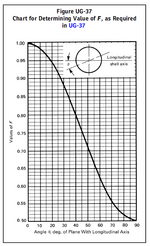
Div. 1 UG-37, Correction factor “F” and Figure UG-37, if code insists it must be 1.0 for re-pad at theta =90 degree, which is the circumferential plane with the longitudinal stress of PR/2t , then “F” shall be 2.0 for re-pad at theta =0, which is the longitudinal plane with the hoop stress of PR/t.
As common knowledge that stress (either tension or bending ) is related to the thickness, regardless it is 2” thick or 1” +1” thick.
That means, code should have treated both directions the same way, F=1 at 0 degree, then F shall be 0.5 at 90 degree, regardless using re-pad of integrally reinforced. If insisting F=1 for 90 degree as in the code, then F shall be changed to 2 at 0 degree due to hoop stress that required twice of the area than at 90 degree.

Your technical thought ? If you are confused what I say, please skip this post.


1752247405493.png


1752247438985.png
 
Do you have access to a 2010 copy of the Code? If yes, then Appendix L Example L.7.7 is a perfect example of the only nozzle configuration I can think of where F would be useful. Certainly better than any explanation I can think of.

The Code has correct values for F so perhaps re-reading carefully will be enough? The figure is looking at the end of the nozzle so the circle is the nozzle neck. Hoop (circumferential) tension is up - down and axial (longitudinal) tension is left-right.

The Code limits Figure UG-37 to self-reinforced nozzles so I don't understand your reference to a repad.
 
Div. 1 UG-37, Correction factor “F” and Figure UG-37, if code insists it must be 1.0 for re-pad at theta =90 degree, which is the circumferential plane with the longitudinal stress of PR/2t , then “F” shall be 2.0 for re-pad at theta =0, which is the longitudinal plane with the hoop stress of PR/t.
Stress along longitudinal axis (circumferential stress joint) (PR/2t) is theta 0 deg and F=1.0.
For theta 90 deg (circumferential axis hoop stress or longitudinal stress joint) (PR/t) is F=0.5.

Yours is the other way around.
 
Last edited:
Trestala,, 0 degree is the longitudinal axis, you will see circumferential stress at the cut plane, which is hop stress and is PR/t. F =1, I have no question as it is the maximum stress plane, need the most reinforcement area. You are making the stress direction wrong.
At 90 degree, the cut plane will be longitudinal stress PR/2t. Due to the 50% reduced stress, code allow F=0.5 so the required area is 50% less than at 0 degree, that makes entirely sense but Code only allow this 50% reduction for integrally reinforced nozzle only. I do not agree with it. The 50% reduction should also be applied to re-pad if used in my opinion, not just for integral nozzles limited by Code.
No change to my original post if someone can reason or has the insight why code limits to integral nozzle only.
 
Trestala,, 0 degree is the longitudinal axis, you will see circumferential stress at the cut plane, which is hop stress and is PR/t. F =1, I have no question as it is the maximum stress plane, need the most reinforcement area. You are making the stress direction wrong.
At 90 degree, the cut plane will be longitudinal stress PR/2t. Due to the 50% reduced stress, code allow F=0.5 so the required area is 50% less than at 0 degree, that makes entirely sense but Code only allow this 50% reduction for integrally reinforced nozzle only.
Yes, I corrected the terms used.

I do not agree with it. The 50% reduction should also be applied to re-pad if used in my opinion, not just for integral nozzles limited by Code.
From ASME Companion Guide
For integrally reinforced openings in cylinders and cones, the value of F may be applied to the required replacement area at any given plane to account for this effect. (An integrally reinforced opening does not use a separate reinforcing element such as a reinforcement plate.) However, the correction factor F is set equal to 1.0 for all openings that are not integrally reinforced.
 

Part and Inventory Search

Sponsor

Back
Top