Dear experts who specialize in nozzle reinforcement:
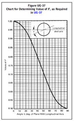
Div. 1 UG-37, Correction factor “F” and Figure UG-37, if code insists it must be 1.0 for re-pad at theta =90 degree, which is the circumferential plane with the longitudinal stress of PR/2t , then “F” shall be 2.0 for re-pad at theta =0, which is the longitudinal plane with the hoop stress of PR/t.
As common knowledge that stress (either tension or bending ) is related to the thickness, regardless it is 2” thick or 1” +1” thick.
That means, code should have treated both directions the same way, F=1 at 0 degree, then F shall be 0.5 at 90 degree, regardless using re-pad of integrally reinforced. If insisting F=1 for 90 degree as in the code, then F shall be changed to 2 at 0 degree due to hoop stress that required twice of the area than at 90 degree.
Your technical thought ? If you are confused what I say, please skip this post.


