Navigation
Install the app
How to install the app on iOS
Follow along with the video below to see how to install our site as a web app on your home screen.
Note: This feature may not be available in some browsers.
More options
Style variation
-
Congratulations TugboatEng on being selected by the Eng-Tips community for having the most helpful posts in the forums last week. Way to Go!
You are using an out of date browser. It may not display this or other websites correctly.
You should upgrade or use an alternative browser.
You should upgrade or use an alternative browser.
Wind Load
- Thread starter dik
- Start date
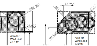
My experience is with AASHTO signs and luminaries spec is what I would apply. Calculate the flat face areas and go from there. I guess you could use the shapes centroid and apply the moment arm to the base and figure the resisting moment required
- Thread starter
- #5
because of the large amount of void.Why the "half the wind load value"?
- Thread starter
- #6
Thanks JAE...I'm always temped to way over-estimate the effective area of things like these.
Not likely... get a Darwin award. I think I will use the full wind load.Can an athletic person jump up and grab a hoop?
- Thread starter
- #7
I think the 'structure' is pretty stiff; I don't think dynamics will be an issue.There's potentially a bunch of stuff vibrating up there,
HTURKAK
Structural
- Jul 22, 2017
- 3,359
Your approach reasonable . I would go with component force coefficients and use the effective area and apply solidity ratio.I was thinking about using the area of the top with a wind load using half the wind load value
Typical Cf could be 2.0 and this value will be divided to solidity ratio ε = As / Ag say if ε=0.33 Cf=2.0/0.33 =6.0 and this value would be applied to net area As.
I would suggest you to look Wind Loads for Petrochemical and Other Industrial Facilities-ASCE.
- Thread starter
- #9
Thanks HTURKAK... I've decided to go for the full wind value. The centroid of the load is close to the corner and unless I can get someone to measure it, my assumption will be a bit of a guess. If it's assembled I'll get them to balance it on an L3x3 to determine the centroid. I haven't done any sums on it yet and I don't know how much of a 'ballast' load to use. I was thinking of using an overturning factor of 2.5.
- Thread starter
- #11
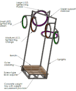
Just decoration and a bench to sit on.Curious. What does the public use it for?
- Thread starter
- #13
Closure on this... I've designed this with a reduced wind load based on an equivalent chain like fence resistance and I've used a 1/10 year return period wind load. I've designed the components for the full wind loading.
I've picked up another reference... ASCE 10... Design of Lattice Steel Transmission Structures, which delves into this in a bit of detail. I've reviewed this and as a guide it goes into great detail and yields results slightly more conservative to the approach that I've used.
I'm content with my approach.
Thanks for providing closure. If I may I want to ask a question:Closure on this... I've designed this with a reduced wind load based on an equivalent chain like fence resistance and I've used a 1/10 year return period wind load. I've designed the components for the full wind loading.
I'm curious what percentage was your final wind load? Eg; vs your initial approach of half the wind load value "using the area of the top with a wind load using half the wind load value"? (My gut feel here is to not go below half the wind load of the total area of the top.)
I design plenty of slender open steel structures. The code I use AS1170 has an Appendix on lattice framed structures which I'd imagine wouldn't differ greatly from ASCE. For the structures I uses which have approximately 70-75% porosity I usually end up with wind loads that are 60%-75% of a clad structure.
It all seems very conservative at first but when you start looking at how much the coefficient of drag varies between shapes it makes sense. My structures are full of 'rectangular' shapes with sharp corners (I-beams, angles, rectangular equipment etc.)

SOURCE: https://en.wikipedia.org/wiki/Drag_coefficient
- Thread starter
- #15
I used 0.5 as originally planned... the equivalent to a fairly 'dense' chainlink fence. I would suggest the porosity was approaching about 90%. The structure is low to the ground and is fairly sheltered. The steel components are not in a dense pattern. Also did not use 0.85 x DL for resistant weight. Actual weights and assumed centroidal distances have to be confirmed. Thanks for the added info...


Last edited:
Similar threads
- Question
- Replies
- 1
- Views
- 7K
- Replies
- 1
- Views
- 3K
- Question
- Replies
- 8
- Views
- 8K
- Locked
- Question
- Replies
- 1
- Views
- 2K
- Replies
- 6
- Views
- 5K

