Tek-Tips is the largest IT community on the Internet today!

Members share and learn making Tek-Tips Forums the best source of peer-reviewed technical information on the Internet!

  • Congratulations TugboatEng on being selected by the Eng-Tips community for having the most helpful posts in the forums last week. Way to Go!

Cantilever Plate bending with UDL

SALTRAM4567777

Structural
Joined
Aug 11, 2020
Messages
97
Location
AE
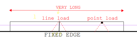
I have a cantilever plate rigidly clamped on one side and free on the other sides, with the plate being very long in the direction perpendicular to the cantilever span. For a point load applied near the free edge, I usually determine the required plate thickness considering load spread at 45 degrees. My question is, for a uniformly distributed load (UDL) along the length of the plate, how should the required thickness be calculated? Do we still apply the 45-degree load spread assumption, or is there a different approach for UDL in this case? Any guidance or references would be helpful.
 
If the load is uniform in the direction parallel to the fixed edge, you'd typically design that on a unit length basis.
 
I am trying but I am not able to attach a sketch. Some issue on my side. It's a UDL Line load acting perpendicular .
 
Treat the plate as a simple cantilever beam. You have a long line load so it is just a simple cantilever calculation with a point load of a unit length x UDL. for a beam that is a unit length wide.
 
Thanks @BAretired for posting the sketch.

I understand simplifying it to a unit-width cantilever beam with UDL. My only doubt is about the effective width. For a point load on a plate, we often assume 45-degree load spread to calculate bending resistance. In the case of a continuous line load along the length, do we still consider same effective 45 degree effective width, or is treating it as a unit-width beam sufficient for plate thickness design?
 
Last edited:
Thanks @BAretired for posting the sketch.

I understand simplifying it to a unit-width cantilever beam with UDL. My only doubt is about the effective width. For a point load on a plate, we often assume 45-degree load spread to calculate bending resistance. In the case of a continuous line load along the length, do we still consider same effective width or beyond unit width, or is treating it as a unit-width beam sufficient for plate thickness design?
I can't understand how it can be anything other than having a unit length to resist a uniformly distributed concentrated load at the end of the cantilever. Please enlighten me. I'm new at this stuff. I only started doing structural engineering 48 years ago.
 
If this case was as simple as you suggest, it would be covered in Roark’s — but it’s not. The closest case is a plate clamped on one edge with the others simply supported. Using a 45-degree effective width from that logic gives a plate thickness far higher than FEA results, making it overly conservative. My question is purely how to determine realistic effective width, so we avoid unnecessary overdesign — not to oversimplify a complex plate bending problem. Years of experience don’t always translate to understanding.
 

Part and Inventory Search

Sponsor

Back
Top