Continue to Site

Eng-Tips is the largest engineering community on the Internet

Intelligent Work Forums for Engineering Professionals

  • Congratulations IRstuff on being selected by the Eng-Tips community for having the most helpful posts in the forums last week. Way to Go!

Vertically stepped wood diaphragm

struct_eeyore

Structural
Feb 21, 2017
268
I'm trying to resolve a wonky diaphragm on a truss with a ~2'-0" vertical step.
The diaphragm can be loaded in both directions. Exterior sheathing is 19/32, interior will be (2)layers of 3/4.
We're obviously loosing the benefit of stagger lapping at least in one direction, but conservatively both.
Other than trying to fit a continuous 2x to connect the plywood corners, are there any other considerations here?
(Chords at outer boundaries have been resolved)
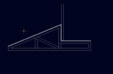

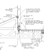
Screenshot 2025-06-02 123954.png
 
Replies continue below

Recommended for you

I'd be inclined to place shear resisting sheathing on the bottom of the truss.
 
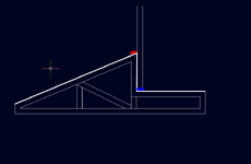
The "step" is just a shear wall. Resolve overturning and provide boundary elements. At the red line, use a coil strap over 2x flat blkg. At the blue line the wall sill plate over 2x flat blocking can be your boundary element. Some of this depends on where your lateral lines below are relative to this truss/floor thing.

1748884389005.png
 
Two blocks within the truss near the sill plate should suffice, shear would go vertical sheathing->vertical block->horizontal block->horizontal sheathing. As mentioned above ensure boundary elements are present and a gratuitous overturning check may be warranted. I try to keep my sill plates only transferring wall shear and load from the floor within the floor but there are many ways to skin a cat when it comes to this stuff.
 
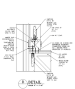
Feel free to run me out of town for this one, but here is the latest iteration. I believe this covers the shear transfer ( the chords are resolved separately on ea end of the wall. ) Any glaring issues (other than the obtuse use of the 6X6)

1.png2.png
 
The "step" is just a shear wall. Resolve overturning and provide boundary elements. At the red line, use a coil strap over 2x flat blkg. At the blue line the wall sill plate over 2x flat blocking can be your boundary element. Some of this depends on where your lateral lines below are relative to this truss/floor thing.

View attachment 10278
I'm having difficulty visualizing your solution.
The diaphragms react to the vertical shear wall, but where does that horizontal (in and out of the paper) go?
 
I trust you have not added that 6x6 (which is PT for some reason even though this looks like a second floor) purely to achieve adequate penetration for your lag screw. This is better done with a through-bolt and blocking in the plenum, but I would go with wood screws through to the truss top chord before doing that.

Also if the wall shown is a shear wall then as long as you have that boundary member at the top of your pitched section fastened to your wall and roof sheathing you have achieved what you want. I see many potential issues in this detail. I recommend you read up on shear transfer, Breyer's design of wood structures is a great resource.
 
Last edited:
Wayne,

Indeed the 6X6 is there just to provide the meat, as a least tolerance-sensitive way to attach all the dowels.
I'm struggling to visualize what you mean by wood screws to truss top chord (?)
 
Seems overly complicated, but I assume you have some very high shear demand with those details. Typically, I just fasten the blocking between the truss top chords to the wall studs and feel that adequately spreads the low roof shear into the attaching wall. As for hold downs, I imagine the shear at the top of the wall will control that and don't worry too much about the slight vertical eccentricity created by this condition. But by all means, add it into the overall overturning consideration.

Of course, there are unique circumstances where more consideration is warranted, but typical this detail comes along with low unit shears at the truss roof IME.
 
Last edited:
Wayne,

Indeed the 6X6 is there just to provide the meat, as a least tolerance-sensitive way to attach all the dowels.
I'm struggling to visualize what you mean by wood screws to truss top chord (?)
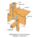
Assuming you have resolved the chord forces and you are trying to develop a continuous positive support over the length of your shear wall, screwing the sill plate to each floor truss would normally suffice. A beefy continuous uplift connection would look something like I've attached minus the wall below, and substitute the floor joist with a piece of blocking to your truss. If you are resisting 500 plf ASD of uplift as you indicate, this might be necessary.

1748893757404.png
 
I'm having difficulty visualizing your solution.
The diaphragms react to the vertical shear wall, but where does that horizontal (in and out of the paper) go?
It goes to the adjacent diaphragm provided you edge nail thru the sill plate and thru floor shtg. The missing information from the poster is where are the lateral elements (shear walls) below relative to this truss.
 
It seems complicated enough that it won't get built properly. Why not run the parallel chord truss thru to the exterior wall and keep the diaphragm flat and just stick frame the slope?
 
Last edited:
The missing information from the poster is where are the lateral elements (shear walls) below relative to this truss.
Yes. I made the gross assumption that there was a VLFR element somewhere under the wall the shear would be dragged into.

If it’s truly to act as a single diaphragm I’d likely first try and do as @JAE suggests, but the trades usually hate that idea.
 
I think XR250 has the right idea. Or a beam or girder in line with the wall. That seems like a weird truss profile to me.

Also, if your loads are light enough, drywall has shear capacity as well so you ceiling may help you.
 
Regarding locating a girder parallel with the wall above. That was the initial layout, however we only have about 3' of total depth for the girder, and it doesn't work for the required span. Hindsight I probably should have pushed for a steel beam, but it's too late for that.

Wayne, I do like the Simpson detail, although I'm not sure if it really simplifies things as it requires more alignment and checking on the contractors part - instead of simply zipping in screws.
 

Part and Inventory Search

Sponsor