CDLD
Structural
- May 20, 2020
- 237
Hi,
I'm working on an existing industrial building, and adding loads to existing crane columns.
How does everyone stand on equally distributing the tractive forces (parallel to rail) to all columns (7 bays).
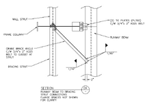
You can see below that the bracket to crane girder connection is slotted.
I assume the rail is held to the crane girder by clamps.
Is the friction from the clamps enough to distribute the tractive force to all columns?

I'm working on an existing industrial building, and adding loads to existing crane columns.
How does everyone stand on equally distributing the tractive forces (parallel to rail) to all columns (7 bays).
You can see below that the bracket to crane girder connection is slotted.
I assume the rail is held to the crane girder by clamps.
Is the friction from the clamps enough to distribute the tractive force to all columns?