Continue to Site

Eng-Tips is the largest engineering community on the Internet

Intelligent Work Forums for Engineering Professionals

  • Congratulations The Obturator on being selected by the Eng-Tips community for having the most helpful posts in the forums last week. Way to Go!

Designing Blind Flange in PV Elite 26 2

MizanAMC

Mechanical
Apr 28, 2024
17
Hi PV Elite experts,

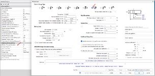
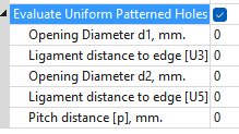
I would like to ask regarding blind calculation considered in this software. i found that the req thickness for the custom blind differ when the "evaluate uniform pattern hole" was clicked. it become thicker when we click this option.
1747297980276.png

Why does this happen? custom blind should be calculated based on UG-34. And the patterned hole will considered UG-36/UG-39. But, by simply clicking this button (not input any hole dimension yet) the thickness already changed.

Or is there multiple ways to calculate custom blind thickness? Hope someone can help.
 
Replies continue below

Recommended for you

If the blind you are designing has bolt holes in it and is being attached as in Fig UG-34(j)/(k), the formula that would be used is equation (2) undre UG-34(c)(2).

The additional loading due to the edge moments result in a thicker flange.
 
If the blind you are designing has bolt holes in it and is being attached as in Fig UG-34(j)/(k), the formula that would be used is equation (2) undre UG-34(c)(2).

The additional loading due to the edge moments result in a thicker flange.
yeah thats true, but after i click "Evaluate pattern hole", the thickness increase.

I think its because of UG-36/UG-39, which evaluate the reinforcement area on the blind (which affected by holes dimension and pitch).

But I don't get how the thickness already increased when the hole size hasn’t even been defined/key in yet.
 
Is the default a B16.5 or B 16.47 blind flange?

In which case going to something bespoke will automatically increase the thickness.
 
It's well known that if you analyse B16.5/47 flanges to ASME VIII they fail. So the program probably recognises that as soon as you click a bespoke item, it automatically calculates the thickness to ASME VIII instead of reading a thickness from a table.
 
It's well known that if you analyse B16.5/47 flanges to ASME VIII they fail. So the program probably recognises that as soon as you click a bespoke item, it automatically calculates the thickness to ASME VIII instead of reading a thickness from a table.
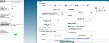
as i mentioned before, the blind did calculated according to ASME VIII UG-34, but when I consider the opening/holes on the blind (by clicking below👇). thickness increased again.
1747732284722.png
This is due to UG-36/UG-39 being considered. However, the thickness should only increase after the hole details are input.
So why do you think it's already increased even though no holes data has been entered yet?"
 
Ok, now that I don't know. Maybe there's some minimum thickness that applies when you drill a hole in of any size?
 
Hi PV Elite experts,

I would like to ask regarding blind calculation considered in this software. i found that the req thickness for the custom blind differ when the "evaluate uniform pattern hole" was clicked. it become thicker when we click this option.
1747297980276.png

Why does this happen? custom blind should be calculated based on UG-34. And the patterned hole will considered UG-36/UG-39. But, by simply clicking this button (not input any hole dimension yet) the thickness already changed.

Or is there multiple ways to calculate custom blind thickness? Hope someone can help.
This sounds more like you are trying to design a Welded Flat Head element and not a Blind Flange.

If you want to design a blind flange then you should select a Flange element and then perform the Flange analysis with a Blind Flange type selected.

1747752144713.png
 
This sounds more like you are trying to design a Welded Flat Head element and not a Blind Flange.

If you want to design a blind flange then you should select a Flange element and then perform the Flange analysis with a Blind Flange type selected.
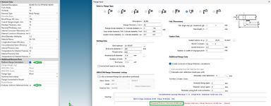
Hi PreVes, I already design it this way. you can refer below.

1) Without click.
1747790175987.png

2) With click (without any hole detail)
1747790297756.png
 
Ok, now that I don't know. Maybe there's some minimum thickness that applies when you drill a hole in of any size?
That was a great point. I think this could be a valid explanation as well. Thanks, LittleInch, for offering a different perspective.

After checking with multiple blind size, the blind min thickness increases by about 25%-28% after I click it. The percentage seems to grow with the size — the larger the blind, the higher the factor.

But I'm not sure if this factor is specified in ASME or if it's just an additional safety margin set by the software developer.
 
Last edited:
Just spitballing here, but have you looked at the calculations print to see what the software is DOING?

Regards

Mike
 
That was a great point. I think this could be a valid explanation as well. Thanks, LittleInch, for offering a different perspective.

After checking with multiple blind size, the blind min thickness increases by about 25%-28% after I click it. The percentage seems to grow with the size — the larger the blind, the higher the factor.

But I'm not sure if this factor is specified in ASME or if it's just an additional safety margin set by the software developer.

Hi everyone, i just go through UG-39 again. and guess what i found?

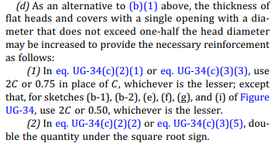
Snip from UG-39:

1747797490430.png

The req thickness of the blind changed after i click "evaluate pattern hole" button is because the software did modified eq from UG-34 (as snip above). By clicking this function, software assume the blind will have at least one hole/opening.

If then I input multiple holes, the software will evaluate them according to the required reinforcement as per UG-39 or UG-36.

Big thanks to everyone who took the time to respond in this thread. I genuinely enjoy discussing with all of you! [heart]
 

Part and Inventory Search

Sponsor