Continue to Site

Eng-Tips is the largest engineering community on the Internet

Intelligent Work Forums for Engineering Professionals

  • Congratulations KootK on being selected by the Eng-Tips community for having the most helpful posts in the forums last week. Way to Go!

Wild differences in manual and FEM calculation results (floor on grade)

nivoo_boss

Structural
Jul 15, 2021
134
Hello everyone!

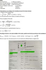
So I'm messing around with a concrete floor. I have a point load of 60 kN acting on an area of 0,04 m². I calculated the Winkler coefficient as 9,2 MN/m³. The floor slab is 200 mm thick, C35/45 concrete.

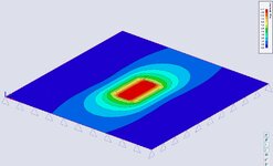
I have a handbook for concrete floors (it's in Estonian, so no point in mentioning the title) so I tried to calculate moments in the slab using formulas from there and also modelled a slab in SCIA Engineer and applied the aforementioned properties to it.

The results are interesting: in SCIA I get a moment of around 12 kNm/m under the load in the slab and using the Westergaard formula from the handbook I get the moment as 2,8 kNm/m. That's a difference of over 4 times. In SCIA I get a bearing pressure of 5 kPa and using the handbook I get a bearing pressure of 157,3 kPa - WTF? I have double checked the units and everything seems to be correct.

Is the Westergaard model so much more different from just a FEM plate on an elastic support that I get so wildly different results or what do you think is the reason?
 
Replies continue below

Recommended for you

Sounds like your soil support under the slab is much less stiff in the SCIA model.

Have you checked to make sure the units on the deflection per force of the elastic foundation are consistent?
 
What area are you averaging the moment over to get your results?
That's an excellent point. One of the frustrating parts of FEM analysis of slabs is the stress risers you can get. The way we usually deal with this is that we don't design for the maximum moment shown on the plot.... But, we average out that moment over a "representative width". Kind of like the ACI "strip method" where an elevated slab is split into column strips and middle strips.
 
That's an excellent point. One of the frustrating parts of FEM analysis of slabs is the stress risers you can get. The way we usually deal with this is that we don't design for the maximum moment shown on the plot.... But, we average out that moment over a "representative width". Kind of like the ACI "strip method" where an elevated slab is split into column strips and middle strips.
Agree with this.

Rules of thumb I have used in the past are to use anywhere from 2x-3x times the thickness of the slab when considering the effective width to average the stresses over.
 
Agree with this.

Rules of thumb I have used in the past are to use anywhere from 2x-3x times the thickness of the slab when considering the effective width to average the stresses over.
Would you do this same 2x-3x width for a structural suspended slab modeled with strips? Typically I do my strips as 1m just to make it easy, is this not correct for cases where you have point/line loads?
 
1m is a bit arbitrary. Would you do 1ft if you were working in imperial? For suspended slabs I average over the column strips given by ACI.
 
In FEM I am averaging over a 1x1 m square. The given result is average. Peak was something like 17 kNm/m.
 
In FEM I am averaging over a 1x1 m square. The given result is average. Peak was something like 17 kNm/m.
A 1m square for a 0.2m thick slab. Right? That seems reasonable.

And, you applying spreading out your 60 kN point load over a 0.04m2 area. Right? Which mean your mesh is about 0.2m x 0.2m, right? That's also reasonable for a 0.2m thick slab....

I have to say that the best way to understand the differences is to delve more into the assumptions that the hand calc method is based on.... And, compare that to the assumptions you made in your modeling.
 
1m is a bit arbitrary. Would you do 1ft if you were working in imperial? For suspended slabs I average over the column strips given by ACI.
If rebar is calculated as in^2/ft, then yea my strips would be 1ft. All of the textbooks I've looked at for slab sizing have presented the area steel as mm^2/m so that's how I've typically done it.
 
You would get different results going from imperial to metric then, because you average your stress out over a wider strip in the metric solution. I guess just another argument in favor of metrification
 
Would you do this same 2x-3x width for a structural suspended slab modeled with strips? Typically I do my strips as 1m just to make it easy, is this not correct for cases where you have point/line loads?
I would use something like this where the code doesn't define another acceptable approach, like column/middle strips in ACI as others have mentioned.

Generally the thinner the slab the more concerned I would be about taking advantage of load spread for flexure/shear design.
 
EngDM: If rebar is calculated as in^2/ft, then yea my strips would be 1ft. All of the textbooks I've looked at for slab sizing have presented the area steel as mm^2/m so that's how I've typically done it.
I'd argue that your method for picking a unit width is arbitrary and not very rational. Below is a write up on this subject that I wrote back when I worked for my previous employer which had recently developed an FEM based slab design program. For what it's worth, most of the write up is mine. However, I think it has been revised a little in the 7.5 years since I left.

Setting the Width of Design Strips​

One of the most important design considerations is how wide to set the design strip. If the width is set too large, the program will average out the moments and shears over too wide of a region. This would result in unconservative design moments and shears. Similarly, if the strip is set too small, the effects of stress risers in the FEM analysis will be over estimated and the design will be overly conservative.​
The setting of the design strip width is truly a matter of engineering judgment. RISA Tech, Inc. makes no endorsement on which methods would be most appropriate.​

ACI Definition of Strips (ACI 318-14 Section 8.4.1/ACI 318-11 Section 13.2)​

This section of the ACI code is really intended for elevated slabs. But, the concepts can be extended into mat foundations as well. The requirement for "column strips" is that the width on each side should be set to 25% of the span length or width, whichever is smaller. Then the "middle strip" is defined to span between the edges of the column strips.​
This method requires engineering judgment for column grids that are not perfectly aligned and rectangular. In addition, when the column strip becomes very small then the middle strip may become very wide so that the entire slab is included in either a column strip or a middle strip.​
The ACI strip method listed above is based on essentially 1/2 of the mid-span tributary lines. The hand calculation methods would have you design for the full tributary moments over this smaller width, which should be conservative. Computer methods (like RISAFoundation) will design for the average moment over the assumed design width, which should result in a more efficient design.​

Zero Shear Transfer Method​

The Zero Shear Transfer method uses the shear force contours perpendicular to the span of the slab to set the design width. This should provide a result very similar to using the mid-span tributary lines, but is a bit more theoretically derived for non-rectangular column layouts. This method is described in greater detail in the PTI publication Design Fundamentals of Post-Tensioned Concrete Floors. Ideally, this method should give design strips of similar width to the ACI strip method. However, it is more rationally derived and should work better for cases where uneven column spacing makes the strip method difficult to apply.​

Zero Moment Method​

In a similar fashion to the zero shear transfer method, the Zero Moment method uses the moment contours to identify where the moment changes sign. This can be used to set the design strip width approximately equal to the distance between zero moments.​

Shear Perimeter Method​

Another basis would be to set the design width equal to the pedestal width plus a distance 'd' or 'd/2' on each side. This will end up being a more conservative assumption for flexure than the other methods listed. As such, it would be more appropriate for situations where shear or punching shear failures are a primary concern. Examples would also include cases where the pedestal is very large, such as for a vertical vessel or grain silo. This is similar, though not identical, to a method given in the NEHRP document GCR 12-917-22 (Seismic Design of Reinforced Concrete Mat Foundations).​

Hybrid Method / Engineering Judgment​

A variation on these methods would be to start off setting the column strip using the ACI strip method. Then, if necessary, the width could be modified based on considering the other methods. This is especially true for situations where the column grid is not aligned or rectangular.​
In addition, when the middle strip widths get too large, they could be set to values closer to the column strip width. The middle strip would normally be centered on the area with the highest mid-span moments. This would neglect lower moment regions between the column and middle strips. Hence, the strips would designed for a higher moment per unit width. This reinforcement could then be extended into the lower moment regions between strips. Or, the user could set up another design strip for these lower moment regions.​
 

Part and Inventory Search

Sponsor