Continue to Site

Eng-Tips is the largest engineering community on the Internet

Intelligent Work Forums for Engineering Professionals

  • Congratulations waross on being selected by the Eng-Tips community for having the most helpful posts in the forums last week. Way to Go!

Replacing Portion of Slab-On-Grade of Pre-Fab Metal Frame Building

Eng_Struct

Structural
Sep 23, 2022
76
Hi everyone,

We're working on a project involving partial slab replacement in a pre-engineered metal building constructed in 1998. The existing 5" thick slab-on-grade (reinforced with wire mesh) includes hairpins from column piers for lateral thrust resistance. Although there is debate on relying on hairpins for lateral thrust through slab-on-grade (wire-mesh capacity, relying on larger tributary widths, saw-cuts causing discontinuity from column to column), the hairpins appear to be old ways of doing things and the building appears to have performed well to date with this detail.

For increased racking loads, we need to replace ~50% of the slab with a thicker, reinforced slab. The new slab will be dowelled into the existing slab using Hilti epoxy anchors, and I plan to expose existing hairpins at the columns and splice them with new rebar projecting into the new slab thus maintaining the existing detail. Unfortunately, the other half of the building (offices, etc.) must remain untouched, so I can’t replace the slab from column to column.

To maintain the tension load path in the slab:
  • I'm designing the dowel spacing (10M @ 8" o/c with 8" embedment) to develop the required tension due to lateral thrust across the joint. Note that the existing design appears to rely on slab tributary width equal to the column spacing for tension load development and this is what I also intend on doing
Cutting a 1 ft strip from column to column and adding tie bars (as done in new construction) is not feasible due to limited access.

Question:

Is there a better or more reliable way to ensure lateral load continuity between the new rebar-reinforced slab and the existing wire mesh slab, considering the constraints?
Also, are there any concerns or lessons learned with relying on epoxy dowels for this kind of tension force transfer across an old slab-on-grade?

Any thoughts or suggestions are greatly appreciated!

Thanks in advance!
 
Replies continue below

Recommended for you

Note that the existing design appears to rely on slab tributary width equal to the column spacing for tension load development and this is what I also intend on doing.

Are you saying the tip-to-tip distance of the hairpin is equal to the bay spacing?

PEMB DL&LL thrust magnitudes are mostly governed by clear span of frames (shorter the better), frame height (taller the better, yes taller), Roof Snow versus Roof Live (less is better) and bay spacing (less is better). There are combinations of these where hairpins work well because the thrust loads are low, not because hairpins are a great design concept. Buildings that clearspan 60' and less in width are less of a concern to me than 100'+ ones.

Before getting advice, what is the estimated DL thrust and what chance will there be that you will get Snow or Roof Live during the process? Wind and EQ are also a concern. You have to deal with the DL thrust the entire time you are under construction.
 
Are you saying the tip-to-tip distance of the hairpin is equal to the bay spacing?
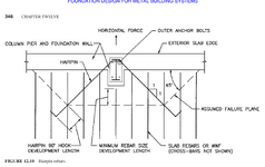
The hairpins are 10 ft long on both side of the pier projecting into the existing slab 1X:2Y slope (y direction parallel to the frame). I am using the slab rebar engaged based on the failure zone below. The width of the developed failure zone with developed slab rebar comes out to be equal to the bay spacing (25ft c/c).

1746409912609.png

Before getting advice, what is the estimated DL thrust and what chance will there be that you will get Snow or Roof Live during the process? Wind and EQ are also a concern. You have to deal with the DL thrust the entire time you are under construction.
I have two span systems with each span being 110ft. The DL load thrust at the outer column is roughly 8.2 kips. The construction is happening during summer so snow or roof live is not a concern. I have checked the footing for sliding and overturning considering unfactored forces and passive resistance and I am getting F.O.S for overturning to be around 1.11 and F.O.S. for sliding around 2 for deadload thrust case when the slab is not present.

I have also checked the wind (unfactored) for temporary condition and getting similiar F.O.S. as above.

I am thinking the structure should be OK for temporary conditions with the above F.O.S. I don't know how would the temporary bracing will look like? Will placing a strut 6 ft above base of the column on the outside suffice?
 
Last edited:
  • I'm designing the dowel spacing (10M @ 8" o/c with 8" embedment)

I am not familiar with the notation of "10M", what does that mean? Is it metric sizes?

I have designed many PEMB foundations but have never had to cut out an existing one that was relying on the hairpins for thrust. The only one I ever had to cut out had the thrust completely controlled by the exterior foundation dimensions and weight.

Since DL & LL thrust do not come from applied horizontal loads, but as a response to the knee areas wanting to distort by rotating inwards as the rafters try to move downward, I would think any force you add along the height of the exterior column would reduce the existing thrust once the transfer of force occurs unless you "preload" your new support in some manner.

I am sure this group could brainstorm several temporary brace ideas.

As far as your new rebar selection, PL/AE is one thing that indicates any thrust method that has to go across the entire slab has limitations. The "L" is so long. For that reason, don't skimp on the "A". Hairpins in reality rely on tension in the slab reinforcing, passive soil, friction from dragging the slab across the soil and a touch of magic fairy dust. I think the slab drag can be more of a factor than we think.

As with many posts, you ask for advice on epoxy and get anything but that. I am not that knowledgeable of epoxies but if you are not in a heavy snow area, your new dowels will not be subjected to a lot of tension overall.
 
Since DL & LL thrust do not come from applied horizontal loads, but as a response to the knee areas wanting to distort by rotating inwards as the rafters try to move downward, I would think any force you add along the height of the exterior column would reduce the existing thrust once the transfer of force occurs unless you "preload" your new support in some manner.

I am sure this group could brainstorm several temporary brace ideas.
I was thinking of putting struts on the outside of the building 6ft above the base of the column with deadman anchors (concrete block etc).

As far as your new rebar selection, PL/AE is one thing that indicates any thrust method that has to go across the entire slab has limitations. The "L" is so long. For that reason, don't skimp on the "A". Hairpins in reality rely on tension in the slab reinforcing, passive soil, friction from dragging the slab across the soil and a touch of magic fairy dust. I think the slab drag can be more of a factor than we think.
I want to rely on friction but part of me thinks that the vapour barrier will reduce friction negating any beneficial effects.

I am not familiar with the notation of "10M", what does that mean? Is it metric sizes?
Yes, 10M is metric size equal to #4 bars in the US.

As with many posts, you ask for advice on epoxy and get anything but that. I am not that knowledgeable of epoxies but if you are not in a heavy snow area, your new dowels will not be subjected to a lot of tension overall.
I am actually in a high snow area. However, based on the tributary width, the tension force per anchor comes out to be small enough to allow for hilti dowels to work with failure governed by concrete breakout.
 
I want to rely on friction but part of me thinks that the vapour barrier will reduce friction negating any beneficial effects.
The VB will decrease it, sure, but the weight of the concrete and relative nonuniformity of the granular subbase will still allow the slab to grip. If your bars are developped into the slab, just think of the mass of concrete that would have to be mobilized to allow the column to move. If the grade beam is also doweled into the slab with like 10M at 16", then you're engaging even more mass (although I typically don't rely on this when doing initial design).
 
Last edited:
As pointed out by EngDM, the VB does change the coefficient of friction but does not make it zero. Also, the surface of the base is not glass smooth. Subgrade drag is real, just try to pull a small piece of concrete across level ground that it was cast on.

One thing I preach about to engineers just getting started is to pay attention to things being tore down. Here is a ripe opportunity to test some "theories" but we are in such a hurry to tear it out and start our new stuff we don't seize the opportunity. Cut everything away from a 10'x10' section and then hook a cumalong to it and to try and estimate how much force it takes to drag the 5" slab a distance of 1". Several of those ASTM approved "Billy Joe" tests and we may gain a little insight and therefore get more comfortable with it. Then look at what your subgrade was. When I was 5, my brother and I watched them tear down a Safeway store in Wichita Falls. It was there that I learned Welded wire mesh belongs on the very bottom of the concrete slab, after all, every square foot we saw them tear out was built that way.😊

I have never checked to see if anyone has done any research on this, but it is greatly needed.

As far as a brace at 6', you must pro-rate the thrust up to account for the shorter distance from lateral force to knee area. Thrust for a 30' tall building is about half of the thrust for a 15' building. Longer leverage reduces needed thrust magnitude.
 
Last edited:
I was thinking of putting struts on the outside of the building 6ft above the base of the column with deadman anchors (concrete block etc).
I’ve done almost exactly this — we used HSS to brace elevated floor slabs while the building was expanded. It doesn’t work so well when the forces get large, though. Deadmans turned into legit underreamed shafts. I’d think about vying for a purely horizontal strut at the column base instead of diagonal at 6ft.
 

Part and Inventory Search

Sponsor