Do you have a small Uninterruptible Power Supply powering your computer?
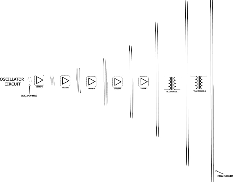
A small, plug in, UPS typically boosts 12 Volt DC up to 120 Volts AC.
An inverter (an oscillator driving a power amp) feeds 60 Hz at 12 Volts, peak to peak to a transformer which steps it up to 120 Volts AC.
The transformer acts as a filter and smooths out the original waveform from the inverter to more closely approximate a sign wave.
The most efficient use of power transistors is a method called Pulse Width Modulation.
The power oscillator outputs a series of square wave pulses of varying width and spacing.
Fed into an induction coil or transformer, The overall RMS of these pulses is a sign wave.
The inherent inductive reactance of a transformer acts as the filter.
The losses in a semi conductor are the least when the semi-conductor is full on. (Or of course full off)
The advantage of PWM is that the semi-conductor is either full on or off.
Hence the series of square waves.
The pulses are generated at a much higher frequency than 60 Hz.
It is possible for the oscillator to generate a sine wave which may then be transformed to a higher voltage, but for a given semi-conductor, PWM will safely pass a much greater current than if the current is modulated to a sine wave rather than switched full on and off by the semi-conductor.
--------------------
Ohm's law
Not just a good idea;
It's the LAW!

