DC Motor - Terminals
(OP)
The terminals of a DC motor are depicted below.
I expected only two terminals (+) and (-), but we have three.

Why are there three terminals? What is the purpose of the extra terminal?
I expected only two terminals (+) and (-), but we have three.

Why are there three terminals? What is the purpose of the extra terminal?
RE: DC Motor - Terminals
For rotation reversal, both the shunt and the series field connections must be reversed together as shown in the connector block (F1, F2, D1, D2 and B2)
Muthu
www.edison.co.in
RE: DC Motor - Terminals
Follow the nameplate connections for CW/ACW direction.
Muthu
www.edison.co.in
RE: DC Motor - Terminals
Yoy will be able to reverse with a two pole contactor rather than a four pole contactor.
--------------------
Ohm's law
Not just a good idea;
It's the LAW!
RE: DC Motor - Terminals
Interchanging A1&B2 will not work in cumulative compound motor. Either you need the 4 way contactor/connector as shown or you need diode control as below.
Forward
Reverse
I have converted such 4 way contactors to diode control with no moving parts for offshore oil rigs cranes.
Muthu
www.edison.co.in
RE: DC Motor - Terminals
I stand corrected. I see my mistake.
--------------------
Ohm's law
Not just a good idea;
It's the LAW!
RE: DC Motor - Terminals
On question Can I connect the cable only to the terminals A1(+) and D2(-)for clockwise rotation and the terminals A1(+) and D1(-) for anti clockwise rotation and leave the terminal F1/F2 without connecting any cable.
In some applications and DC motor where armature and excitation voltage are same value , it is possible to connect the terminals A1 and F2 for anti clock rotation and connect at ( -) polarity with ( +) polarity at F1 - D1 .
RE: DC Motor - Terminals
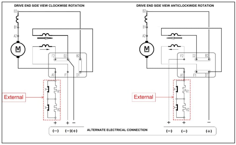
We have an armature winding (the big "M" on the original diagram) connected between A1 and A2.
We have an interpole and/or a poleface winding (the inductor looking thingy in the upper left) connected between B1 and B2.
We have the main shunt field winding (the inductor thingy connected between F1 and F2).
We have the series filed winding (the inductor thingy connected between D1 and D2).
For correct operation, the current has to flow through each winding from terminal 1 to terminal 2. This means the series field ADDS to the main field, hence the term "cumulative". The "compound" terminology just means there is a series field present.
The reason the connection is shown with F1 and A1 as separate inputs is because it is not uncommon for these to be supplied at significantly different voltages (armature voltage is typically 2x-5x the field voltage) and current variation in each winding is governed by different things: by mechanical load, in the case of armature and by speed in the case of field.
Bottom line - you CANNOT leave F1-F2 unconnected as the machine will experience catastrophic overspeed.
Converting energy to motion for more than half a century
RE: DC Motor - Terminals
The typical variable speed DC motor had a constant voltage field supply and a variable armature voltage to vary the speed.
I have seen a lot of DC motors. None of motors that I saw and worked on had discrete interpole connections.
The interpole was always permanently connected to the armature circuit and included in the circuit between A+ and A-.
Given the possibility of serious commutator damage that may occur if the interpole is accidentally reversed, it makes sense to connect it permanently.
I have seen many motors where the interpole was not even shown on diagrams although it was present.
There is no reason to ever change the polarity relative to the armature of the interpoles.
Series windings, on the other hand may be connected as cumulative compound for better torque under load or differentially compound for better speed regulation. (differentially compound may result in motor runaway in the event that the shunt field is lost.)
Also the series winding connections must be reversed relative to the armature if the motor is reversed.
--------------------
Ohm's law
Not just a good idea;
It's the LAW!
RE: DC Motor - Terminals
I saw intention of a colleague to solve power supply of the DC motor with only two wires, and I remembered that I had seen such a solution, but my comment is not an obstacle for this DC motor to be solved that way.
Good luck
RE: DC Motor - Terminals
Historically, before the development of power electronics, larger DC motors were started with resistance in series with the armature to limit the starting current.
The resistance was cut out in steps as the motor accelerated.
In variable speed applications, a motor generator set was used to supply the armature current.
The applied voltage was ramped up by controlling and varying the field of the generator.
In small DC motors such as are used in the automotive industry, the supply conductors act as the starting resistance and lower the starting current. Small DC motors may also have a relatively higher armature resistance.
--------------------
Ohm's law
Not just a good idea;
It's the LAW!