The plate force results can get a little difficult to explain. Let me see if I remember correctly. I believe I do, but I cannot be 100% certain. You'd want to talk to Roger to be sure. But, he's not with RISA anymore either. I don't know if anyone in their tech support group (maybe even within their development staff) will truly know this anymore. There's just no one who's really got all that much experience left over there (IMO).
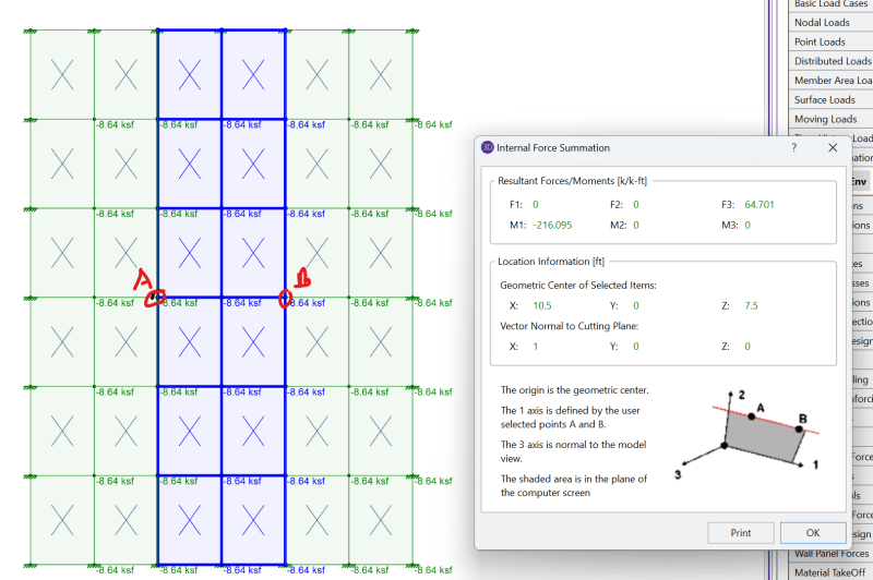
1) Nodal Forces are true forces. That's the force (or moment) transferred into or out of the plate at that node. This is what the basis is for the internal force summation tool.
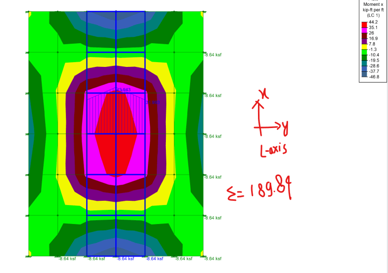
2) Internally, the "plate forces", on the other hand are calculated at each of the 4 Gaussian integration points of the plate. When averaged, these are reported as the plate force results for the natural center of the plate (in the spreadsheets). Keep in mind this isn't a true force, but a plate force meaning that it's a force (or moment) per unity length. It's also important to realize that these plate forces are based on the local x, y and z directions of the plate.
3) For contouring, RISA starts by determining an "approximate plate force at each node". This is done by averaging the nearest gaussian integration point for every plate connected to that node (this will be important later). Again, this is a "plate force". So, it's based on a per unit length basis.
4) For contouring, the next step is to use a interpolation scheme to interpolate the plate forces from one plate corner to the next. I believe this interpolation means that the 'approximate plate force at each node' can affect not just the plate it's connected to, but the plates next to those ones as well.
Potential pitfalls for contouring:
A) Remember in item 2 where I pointed out the plate forces were based on local the local axes of the plate? And, item 3 where I pointed out that the "approximate plate force at each node" is based on ALL the plates connected to that node. Well, what happens when not all of the plates connected to that node have their local axes pointed in the same direction? Well, that messes up the contouring pretty badly.
B) Plate contours don't do a great job right at point of discontinuity. That could be a Joint load. That could be a boundary condition point or such. Note: It's actually not that difficult to get it right at boundary conditions. That's why if you model a cantilever plate in RISA and model the same one in other programs (SAP2000, for example) you'll get worse contour results at the boundary conditions in RISA. But, everywhere else they'll look identical.
Another thing to keep in mind (which I believe applies to that model you've shown) is that plate elements are much more mesh dependent than beam/column elements. By, that I mean that you'll get good force and deflection results with a single Fixed - Fixed beam model. But, if you mode the same thing with a plate element you need to mesh it a lot.
The rule of thumb I use is you want (as a minimum) three plates between points of inflection. Your model is probably right at that minimum. Maybe below it. I think you could sub-mesh your model 2x2 to see improved results.
Caveats:
a) I used to be the VP of Engineer / Tech Support for RISA. I was there for 15 years. But, left when they were sold to Numbchek and Amber took over management. There will always be some hard feeling about how Nubshuck and Amber treated me during that transition. So, I have some bias against them that may affect the way I feel about RISA products in general.... And, even more so about how they view their customers.
b) I now work for RISA's most prominent competitor (CSI which writes the SAP2000 software). So, I definitely have a financial interest in the promotion of their products. Again, this is another potential source of bias for me. Therefore, take any comparison of RISA / SAP2000 that I make with proper consideration of my bias.