TugboatEng
Marine/Ocean
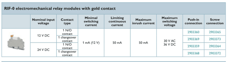
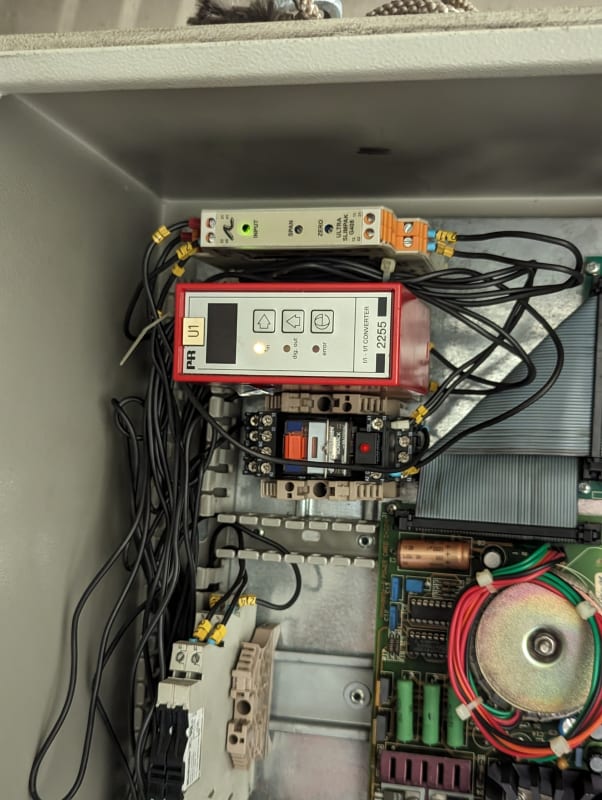
I have an application where I need to interlock a 4-20mA control signal but interrupting the signal with a relay caused a nuisance alarm. I need to establish a minimum signal level.
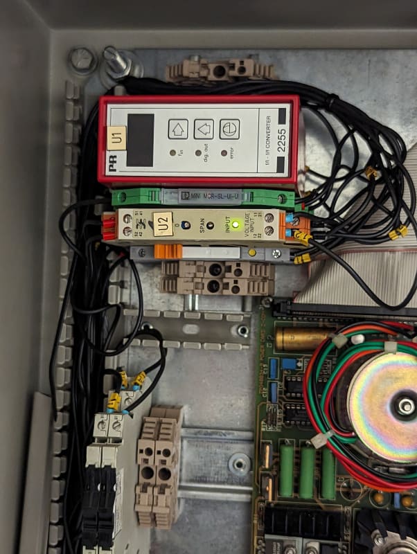
For the details, this is a clutch interlock on the throttle of a diesel engine. The interlock is a relay operated by a pressure switch. The controller outputs 0-10V for the throttle signal, there is a converter to 4-20mA. The interlock is currently on the 0-10V side and is not reliably passing the voltage signal. I proposed moving the relay to the 4-20mA signal. I have confirmed through the manufacturer of the controller that the relay should be installed in the 4-20mA leg. However, it causes a nuisance alarm.
As a solution, I'm thinking of adding another 4-20mA isolator and to install the relay between the two isolators. I need an isolator that will take 0mA in and output 4mA. I purchased a Phoenix Contact MINI MRC-SL-I-I as it lists having both 0-20 and 4-20 in/out but I see now that it is not configurable (out=in). I don't think it's going to work. I may try the MCR-SL-UI-UI-UI.
Any thoughts on this?