Aerodynamic smoothness of rivets
(OP)
Working on a turboprop aircraft whose SRM defines aerodynamic smoothness in terms of maximum protrusion beyond the skin. It's tight enough that everyone says you can't have protruding head rivets. However, the purpose of the rivets is a doubler, and the doubler is a reinforcement to an antenna, and the antenna is a blade 16" long with a 10" chord. A big shark-fin blade that has plenty of drag. I am looking at the overall situation and considering whether the rivets really have to be flush for "aero smoothness" when the antenna will add many pounds of drag in the free air stream.
Other considerations:
-Fracture mechanics of countersunk rivets is poor compared to protruding heads
-The skin is very thin, chem-milled. Even low-profile rivets (NAS1097) are knife-edge in 0.032 thick skin.
-Blade antenna is stabilized by rigid internal structure but that means there are out of plane loads on this doubler. Small, but not zero.
-Boundary layer thickness in the area is at least 1/4" (this is not a guess, I have experience with this)
I think I'm gearing up for fight but is there really one to be had?
If the purpose of the smoothness requirement in the SRM has more to do with blending edges of repairs, and overall fuel economy of the aircraft in service, and "nice to have" then could an argument for structural integrity beat it?
RE: Aerodynamic smoothness of rivets
Can you add an outside doubler, countersink into the doubler, and then add aero filler on the doubler leading edge?
RE: Aerodynamic smoothness of rivets
Is the antenna in an area where aero smoothness is not really important?
Do you have an aero expert on staff?
RE: Aerodynamic smoothness of rivets
You are correct about the STC, but my style is to refer frequently to SRM practices in the substantiation. It would be unusual to avoid the particular section about aero smoothness when so many other SRM practices are referenced. Maybe that's the issue in a nutshell, the inconsistency.
I do have an aero expert but more of a loads and dynamics person, not had to make a judgement like this before. The boundary later investigations I've done before tell me enough that a patch of several dozen rivets isn't going to affect the speed or fuel consumption of the aircraft one jot. The drag from the antenna is an order of magnitude more.
RE: Aerodynamic smoothness of rivets
Who says that your references always must be affirmative?
Seems to me like you have valid reasons for not following the SRM. So....
Although the SRM call for flush rivets, in this case protruding head rivets are used because:
- The drag from the antenna is much larger than any contribution of the rivets.
- Fracture mechanics of countersunk rivets is poor compared to protruding heads
- The skin is very thin, chem-milled. Even low-profile rivets (NAS1097) are knife-edge in 0.032 thick skin.
- Blade antenna is stabilized by rigid internal structure but that means there are out of plane loads on this doubler. Small, but not zero.
- Boundary layer thickness in the area is at least 1/4"
RE: Aerodynamic smoothness of rivets
Or does the aero smoothness requirement apply universally?
Can you give any indication of the type?
RE: Aerodynamic smoothness of rivets
This is when I would recommend/specify... in rough order of preference...
Dimpled outer skin into dimpled or countersunk underside doubler... then buck-install solid aluminum flush rivets. WARNING: Cold dimpling May NOT be possible with 2xxx-T6 or 7xxx-T6 sheet metal.
Protruding shear/small-head titanium Hi-Loks with aluminum collars 'wet with sealant' in transition-fit holes.
NAS9306 FLANGED DOME HEAD blind rivets [= 'Unisink' blind rivets, CherryMax style = CR3245, CR 3255]
https://res.cloudinary.com/engineering-com/image/upload/v1686843456/tips/CA-1011_CherryMax_manual_y27903.pdf
Or a protruding shear-head [low height] titanium blind bolts[ Huck or JO-Bolt style]
https://res.cloudinary.com/engineering-com/image/upload/v1686843775/tips/CA-1010_Titanium_Blid_MaxiBolt_xrnhw6.pdf
Of course, MS20470 rivets can be installed and the protruding heads CAREFULLY milled down ~to 66% height.... to reduce height and look 'smoother'... but retain adequate head strength.
Regards, Wil Taylor
o Trust - But Verify!
o For those who believe, no proof is required; for those who cannot believe, no proof is possible. [variation, Stuart Chase]
o Unfortunately, in science what You 'believe' is irrelevant. ["Orion", HBA forum]
o Only fools and charlatans know everything and understand everything." -Anton Chekhov
RE: Aerodynamic smoothness of rivets
If you don't have skin thickness for a CSK (even an LZ4) then your two choices are protruding head rivets (yuch) or an external dblr. Yes, this will require (if in the pressure cabin) a LFEC inspection, but this shouldn't be a problem. Of course you can extend the dblr beyond the stringer and so have an internal visual/HFEC inspection.
"Hoffen wir mal, dass alles gut geht !"
General Paulus, Nov 1942, outside Stalingrad after the launch of Operation Uranus.
RE: Aerodynamic smoothness of rivets
The definition of the critical zone is interesting in this case. Looking carefully, I found that the zone of the antenna doubler is only inches away from the non-critical zone. Basically, any area on the fuselage skin forward of the spar is critical for aero smoothness, while aft of the spar only the upper side is critical. This antenna is on the bottom just two bays forward of the spar. Any downstream effects of this installation just 24" farther back would be only slightly less than the effects at this position (and the existence of any effect is very dubious).
Another thing I noticed while checking the details: the aero smoothness standard accepts anything less than 0.030" above the skin surface. Since the head of a MS20470AD4 is 0.05" high, this is how I came to question using them. Are there any other types of protruding-head solid rivets that don't have such a large head? I've heard of a "Briles" rivet but never seen one in the wild. The Unisink fits under the threshold, but using blind rivets on the skin would probably cause more trouble than it solves. This is probably a blind alley (oh, pun intended) because even if I can find special rivets, there won't be strength data for design, and the guys with the rivet guns will need special tools to drive them!
Shaving the heads, as Wil suggested, sounds preferable. That could be a note on the drawing presented as an option to the installer.
This turboprop has been described as the pick-up truck of the sky, so I'm not daunted by the "ugly" argument.
RE: Aerodynamic smoothness of rivets
Hmmm... what fasteners are being installed and does the NTDM reference standard account for the fastener head overhang?
I see a lot of people get caught out by that... in analysis they assume detectable length is whatever the reference standard says, but usually for HFEC it is XX inches PAST the fastener head.
LFEC is is usually standardized from the SHANK.
Add on top of that, you need to be inspecting for cracks originating at the faying surface between the doubler and skin. So if your doubler is internal, you should be using external MFEC, which is not as sensitive as HFEC.
So if your options are:
1. Design with internal doubler and use external MFEC around fastener heads -or-
2. Design with external doubler and use external LFEC through the doubler
It is probably close to a wash in terms of inspectability tbh.
I see this all the time with DTA reports, people don't pay attention to the NDTM reference standards and set their detectable flaw size incorrectly.
Keep em' Flying
//Fight Corrosion!
RE: Aerodynamic smoothness of rivets
Edit: Noting that some times SRM repairs give themselves outs againest other restrictions in the SRM.
RE: Aerodynamic smoothness of rivets
Instead did you mean: an inspection internally using mfec, through the doubler, for a lead crack in the skin?
(Typ assume cracks are growing in the worst case location, in this case - always at the faying surface regardless of doubler on inside or out. Assuming also antenna not removed and doubler gage> skin)
RE: Aerodynamic smoothness of rivets
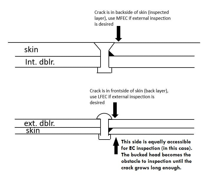
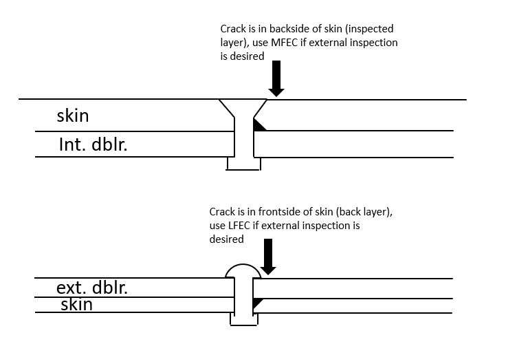
This is what I mean (excuse the hastily drawn figures):
My assumption is that we are always inspecting the skin, not the doubler, since this should be the critical detail for load transfer in the reinforcement.
Keep em' Flying
//Fight Corrosion!
RE: Aerodynamic smoothness of rivets
https://res.cloudinary.com/engineering-com/image/upload/v1686974105/tips/FAA-AIR-90-01_Tom_Swift_Repairs_to_Damage_Tolerant_Acft_qs4mzf.pdf
Regards, Wil Taylor
o Trust - But Verify!
o For those who believe, no proof is required; for those who cannot believe, no proof is possible. [variation, Stuart Chase]
o Unfortunately, in science what You 'believe' is irrelevant. ["Orion", HBA forum]
o Only fools and charlatans know everything and understand everything." -Anton Chekhov
RE: Aerodynamic smoothness of rivets
You are quite right, the head must be accounted for, whether it is flush or protruding. And special-head rivets may be larger in diameter if lower in profile, thus delaying the detectability threshold. I believe the standard inspection tools on this aircraft for its external skin (per OEM insepction manual) is HFEC, which is unable to "see around corners".
I've taken the liberty to edit your diagram, since it's suitable to illustrate my external doubler considerations, too. My design concerns the lower skin, so in my application the diagram should also be upside-down. I didn't bother turning everything around!
Another consideration, and this may come out of left field for many of you, but I often see it on aircraft of this type: a self-adhesive polymer protective covering on the lower skin. It's most commonly seen on aircraft equipped to land on unpaved runways, to protect the belly skin from rocks thrown up by the nosewheel. It's one part of a "gravel kit" modification that many of these planes that I see. This polymer coating is about 0.04" (1mm) thick and it must be horrendous to remove for skin inspections. There might be more happy customers if I make this antenna design inspectable from the interior.
RE: Aerodynamic smoothness of rivets
"Hoffen wir mal, dass alles gut geht !"
General Paulus, Nov 1942, outside Stalingrad after the launch of Operation Uranus.
RE: Aerodynamic smoothness of rivets
"Hoffen wir mal, dass alles gut geht !"
General Paulus, Nov 1942, outside Stalingrad after the launch of Operation Uranus.
RE: Aerodynamic smoothness of rivets
"Hoffen wir mal, dass alles gut geht !"
General Paulus, Nov 1942, outside Stalingrad after the launch of Operation Uranus.
RE: Aerodynamic smoothness of rivets
Yes, I was considering an external doubler to try to make the inspections happen from the inside. Visual and HFEC.
Found some trouble with that idea today, where everything in "chapter 4", IE the Maintenance Planning Manual that defines airworthiness inspections, specifies all of the visual inspections be done from the exterior. I couldn't find any internal skin inspections. That's a bad start, even if I do ultimately plan to define scheduled inspections with HFEC.
In the same manual is a "note" about the gravel protection and, quite confusingly, it does not say to remove it. Instead it says to inspect the protective layer. Umm... but cracks grow whether it's covered or not... It is definitely not transparent. I'm still pondering the meaning of that statement, in case I haven't understood it or need information from somewhere else to make sense of it. I certainly have more reading to do, of course.
RE: Aerodynamic smoothness of rivets
"surely" there are visual inspections of the IML, like for corrosion ?
"surely" you can define your own inspections ? maybe as a "special detailed visual" ?
"Hoffen wir mal, dass alles gut geht !"
General Paulus, Nov 1942, outside Stalingrad after the launch of Operation Uranus.
RE: Aerodynamic smoothness of rivets
and... Don't call me "surely" ;)
RE: Aerodynamic smoothness of rivets
"Hoffen wir mal, dass alles gut geht !"
General Paulus, Nov 1942, outside Stalingrad after the launch of Operation Uranus.
RE: Aerodynamic smoothness of rivets
Something that I've noted among the 3rd party "modders" of the aviation industry is that there are certain individuals with out-sized influence on how the specialists in a given area behave. Since you and I are a continent apart, we are in different regions with different regulatory offices to report to. There are different individuals setting the standard at each regulator's office. Even if everyone is using Safarian's methods (and we aren't) many engineers who write these reports can't self-approve them, and fewer (if any) can approve the associated airworthiness limitations. So there's always someone looking over our shoulders. These engineers doing the government oversight get the last word, every time. That's how I can end up with a different methodology than you have to use, even if we took the same courses and read the same books.
When you suggest that nobody is "looking for cracks under the rivet head..." Oh golly, you aren't talking about Safarian or Eastin or any of that clan, are you? The folks looking over your shoulder may have steered you to use substantially different methods than my benefactors. If I ventured to omit such a detail...
Your other point about visually inspecting for cracks is well taken, and the crux of my decision today. Today's work on the design has led me to choose not to pursue an external doubler after all. The antenna is large enough to require reinforcing members (intercostals) on the internal structure. The combination of an external doubler and internal intercostals plus some other reinforcement bits will make it difficult to complete an inspection visually or by eddy current. The structure would cover both sides of the skin, preventing complete coverage of the inspection without complicating the inspection task to see 2 layers down. Not worth it.
The internal doubler concentrates all of the additional structure on the inside of the skin, leaving the outer skin surface completely exposed for DVI and HFEC (after removing the antenna of course).
RE: Aerodynamic smoothness of rivets
design is always compromise. Sure, leave the OML clear, and if you're not using CSK rivets then you've avoided one compromise. But you've still got three layers ? (skin, internal dblr, internal longeron ?). In my mind, a big advantage of an internal dblr is that you don't affect the OEM inspections (if you inspect the cabin shell); of course you're adding your own inspections.
"Hoffen wir mal, dass alles gut geht !"
General Paulus, Nov 1942, outside Stalingrad after the launch of Operation Uranus.
RE: Aerodynamic smoothness of rivets
RB, just curious... how are you able to typically support ICAW based on visual inspection as the sole inspection option?
I understand that if you look at the SSID or MPD for commercial aircraft they are usually rife with GVI and surveillance inspections. And even service bulletins and DTR check forms will include visual inspections.
But in my experience they are generally used as a supplementary source in combination with other inspections to improve the DTR of a detail.
In the past when I have specified visual inspections in an ICAW it has been in situations where I was supplementing instrumented inspection, or I was in an SSI affected area or something where I wanted to layer the existing inspection with an additional one.
For something like a skin reinforcing doubler with interfastener crack details, etc. I would not generally expect that analysis would support a visual-only inspection program. I guess it depends on the net section width you assume if you are critical for residual strength. But typical POD requirements would put the detectable flaw length for DVI at no less than 1.00 inches. For a lot of details I would think once the crack reaches 1 inch long, you've not got enough life left to support 3 intervals between detectable and critical.
Keep em' Flying
//Fight Corrosion!
RE: Aerodynamic smoothness of rivets
visual inspections are perfectly legitimate limitations. Many OEMs use them. Of course with an external doubler you need LFEC which isn't that big of a problem (to our customers) ... no more than a typical OEM repair. Most of our mods (installing antennas) have little structural impact, and we kill it with Aluminium. The main reason for the dblr is to avoid questions if we didn't use one and to hide the CSKs of the rivets; it really does little to reinforce the hole (1" dia).
"critical crack length" ? "residual strength" ?? yeah, I know what you mean but I'm never close to those limits. Typically I'll have 1 pitch crack growth from 0.05" as the detectable (threshold) time and another pitch (making 3 in total, as the uncracked side of the original hole starts up) for the repeat interval. Max stress intensity less than 50 ksi.in^0.5 ... "nah bother" ... not worth continuing the analysis for a slightly longer interval.
"Hoffen wir mal, dass alles gut geht !"
General Paulus, Nov 1942, outside Stalingrad after the launch of Operation Uranus.
RE: Aerodynamic smoothness of rivets
I have honestly never heard of that being used as a threshold setting criteria. In my experience with FAA ACO guidelines, if you are using LEFM to set a threshold it would be the time from initial to critical length divided by 2. There are situations where your criteria might be conservative, but very likely not if you are using a visual only inspection. With a visually detectable length of 1 inch and an initial flaw of 0.05", the overwhelming majority of the life will be spent before the crack is detectable and you could be well advanced into Region II before you ever start inspecting. My point is if you are using DVI only, it's not going to leave you much time to get multiple inspection opportunities in and your repeat would have to be very short.
Maybe that's a bit tongue in cheek, but the primary purpose of the doubler is to provide a structural load path for the skin load in absence of the removed material, no? Even if the cutout is "small" at 1 inch.
So I understand that you are cutting the analysis off before failure due to residual strength or critical stress intensity, stopping at 3 pitches based on some kind of patching technique I assume. But,
1. I don't get what you mean by "another pitch (...) for the repeat interval. Are you taking that time and dividing it up? Or are you just saying the time from detectable length to 3 pitch length is your repeat? Because I don't see the relevance of that. Regulations would dictate that we need multiple inspection opportunities, right?
2. "as the uncracked side of the original hole starts up"... Again, maybe a difference between FAA and Transport Canada, but isn't the requirement to examine the simultaneous action of primary and secondary flaws?
Yeah, but not as the primary inspection basis for a reinforcing repair. I'm quite familiar with SRM standard skin repair inspection requirements. They might include visual inspections, but they always have some form of instrumented inspection. It's really about layering the inspection options to achieve the desired DTR.
Not trying to overly scrutinize / criticize. It's just I've worked in the FAA system a lot and with a lot of DERs, a lot of STCs and major repairs, and there are pretty standard ways of doing things. So I'm always curious when I see different techniques being used.
Keep em' Flying
//Fight Corrosion!
RE: Aerodynamic smoothness of rivets
my 1 pitch detectable gives me plenty (or sufficient) time for repeats. We have low cycle planes, typically I get 5 year repeat intervals.
"Maybe that's a bit tongue in cheek" ... nope, a riveted on doubler does little to reduce the stress concentration at the hole; ok, it typically reduces the skin stress to 2/3rds. The most it does it to produce a higher fatigue issue at the load transfer rivets, which is what we're inspecting.
I start from 0.05" a hole loaded hole. grow to the next fastener. The next fastener has a "continuing damage" flaw, and the original hole has a 0.005" continuing damage. grow this to the next hole (3 pitches in total). inspection intervals are enough, residual strength is plenty; extra analysis not worth it.
"the requirement to examine the simultaneous action of primary and secondary flaws" ... yes, as explained above. The initial hole has a 0.05" and the others have 0.005". The initial hole is going to initial a crack at some time, but I don't "need" a 0.05" and a 0.005" at the initial hole.
"Yeah, but not as the primary inspection basis for a reinforcing repair." .. well that depends on the reinforcement. In the case being discussed (yes, let's get back to that !) with an internal doubler, I'd be happy with an external visual of the skin (being FCBS). Depending on design details I might not need inspection of the dblr (at all).
I've worked with OEMs and now with a "mod shop". What we do isn't the same as an OEM (mostly because we don't have the detailed data the OEM has). So we make simple conservative assumptions and analysis. Most of our work is on fuselage mods, which greatly simplifies the fatigue spectrum. (Btw, I hate the Chicago Office methodology, even though I know many people use it and it is of course "blessed" by the FAA.)
"Hoffen wir mal, dass alles gut geht !"
General Paulus, Nov 1942, outside Stalingrad after the launch of Operation Uranus.
RE: Aerodynamic smoothness of rivets
Keep em' Flying
//Fight Corrosion!
RE: Aerodynamic smoothness of rivets
"Hoffen wir mal, dass alles gut geht !"
General Paulus, Nov 1942, outside Stalingrad after the launch of Operation Uranus.