Tek-Tips is the largest IT community on the Internet today!

Members share and learn making Tek-Tips Forums the best source of peer-reviewed technical information on the Internet!

  • Congratulations cowski on being selected by the Eng-Tips community for having the most helpful posts in the forums last week. Way to Go!

GD&T tolerance

Status
Not open for further replies.

nedders

Mechanical
Joined
Feb 15, 2023
Messages
13
Location
GB
Hi

I haven't used Geometric tolerances for a while, so I just wanted to double check I'm not going insane

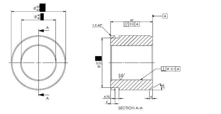
I stumbled across a drawing (see attached / or below post), and I'm pretty sure the geometric tolerancing is wrong.

1) The parallelism looks to be on a wrong face?

2) Also, personally I would have thought it would have been better to datum A the external of cylinder and put a concentricity on the internal, rather than a perpendicular?

Thanks
 
 https://files.engineering.com/getfile.aspx?folder=770750d5-dbfd-477a-9306-377e342958fc&file=tolerances.jpg
tolerances_lhtzui.jpg
 
You might get some better answers if you post this in the Drafting and GD&T forum:


That being said, I see no problem with where the 'A' datum has been established nor the use of the parallelism constraint. True, it would seem that there is a missing concentricity constraint, perhaps even two, as the bottom of the groove needs to be constrained as well, plus the walls should be parallel to the 'A' datum as well, but then we have to assume that there are default tolerances, in which case, the only tolerances needed on the drawing are those which are either more or less precise than what the defaults standards would indicate.

John R. Baker, P.E. (ret)
Irvine, CA
Siemens PLM:

The secret of life is not finding someone to live with
It's finding someone you can't live without
 
Thanks. Moved to the other forum, can close this one now
 
Status
Not open for further replies.

Part and Inventory Search

Sponsor

Back
Top