What would be the transverse shear reinforcement in this case?
(OP)
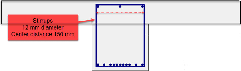
I have a cross section as seen below, where the stirrup bars have a 12 mm diameter and center spacing of 150 mm. If I am asked what the transverse shear reinforcement is in the top part of the cross section (marked with black rectangle), is that the distance I've marked with the arrows in the middle of the stirrups?

Edit: What would be the transverse reinforcement of the entire cross section "T"?

Edit: What would be the transverse reinforcement of the entire cross section "T"?
RE: What would be the transverse shear reinforcement in this case?
Normally, for vertical load / shear, the shear reinforcement in the top will be the same as it is in the bottom: 12mm @150mm. This is the same for a T-beam as it would be for a rectangular beam.
Some codes do have limitation on how far apart stirrup legs can be spaced within a flexural member. If that's the question being answered then, yes, the dimension highlighted in your sketch would apply.
RE: What would be the transverse shear reinforcement in this case?
As an aside thought, if that is the real cross-section then I would be expecting to see more intermediary vertical links to support the various bundles of bars
Our code has limitations on how far apart you can have vertical links in order to confine the reinforcement...
It seems like you have 11 bars floating around on the bottom, I'd be amazed if you don't need intermediary links to restrain at least a few of them
RE: What would be the transverse shear reinforcement in this case?
At some point, simply using larger bars makes far more sense.
----------------------------------------------------------------------
Why yes, I do in fact have no idea what I'm talking about