×
INTELLIGENT WORK FORUMS
FOR ENGINEERING PROFESSIONALS

Contact US

Log In

Come Join Us!

Are you an
Engineering professional?
Join Eng-Tips Forums!
  • Talk With Other Members
  • Be Notified Of Responses
    To Your Posts
  • Keyword Search
  • One-Click Access To Your
    Favorite Forums
  • Automated Signatures
    On Your Posts
  • Best Of All, It's Free!

*Eng-Tips's functionality depends on members receiving e-mail. By joining you are opting in to receive e-mail.

Posting Guidelines

Promoting, selling, recruiting, coursework and thesis posting is forbidden.

Students Click Here

Torsion on truss Mutually opposed lacing system
2

Torsion on truss Mutually opposed lacing system

Torsion on truss Mutually opposed lacing system

(OP)
Hello,

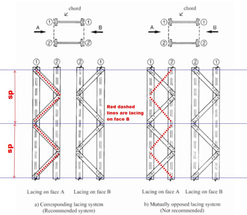
Studying Eurocode 1993 1-1, i've found, in topic 6.4.2.2 (Constructional details), the recommendation about the orientation of the lacing planes on built-up columns shown below.


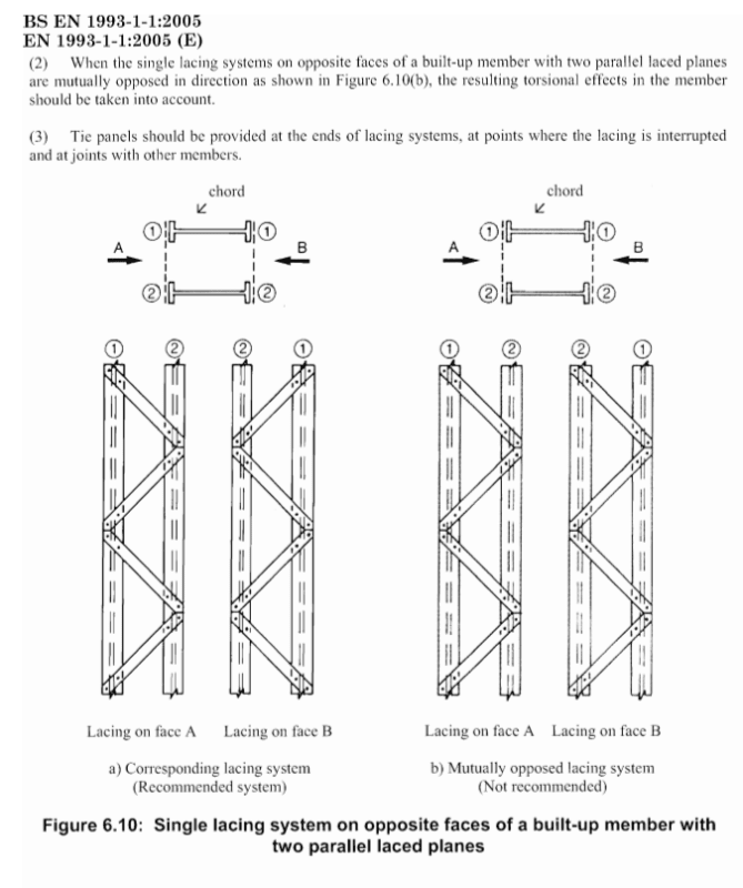
I've never used this mutually opposed lacing system but i see it in my region with a reasonable frequency and i think nobody consider the torsional effects. I'm planning to do some research on this topic and maybe write a paper about it if i verify that the reduction on member strength due to this torsional effects is too great and if there's no paper already written on the subject. Is anyone aware of such paper or has analyzed a structure of such type?

If Eurocode brings a recommendation about it and says that there are torsional effects, i think that someone has done research on the topic but i couldn't find it. Also, Would you suggest a frame analysis with the diagonal ends offset or a complete FEM analysis.

Thank you in advance.

RE: Torsion on truss Mutually opposed lacing system

(OP)
Someone?

RE: Torsion on truss Mutually opposed lacing system

Loading looks symmetrical about the center of gravity. Not seeing torsion.

RE: Torsion on truss Mutually opposed lacing system

(OP)
I interpreted that when the built-up column(or a truss with this configuration) is subjected to bending, one of the diagonals will be subjected to tension and the other one to compression, and since they are not on the same plane, there will be torsion.

Am i interpreting this wrong?

RE: Torsion on truss Mutually opposed lacing system

Under axial load or bending, the lacing members will carry some of the compression/tension due to compatibility with the main members.

Under pure compression or tension, if the lacing members are mutually opposed, then the transverse component of the lacing members act in opposite directions (b), giving torsion shown below.


Under pure bending, I imagine you would get the same torsion effect when you have the corresponding lacing configuration (a).

To work out the force carried by the lacing members, either check it with a frame model or I would also recommend looking at Figure 3.7 in Design Guidelines For Steel Trapezoidal Box Girder Systems, which you should be able to find online easily. Those equations are set up to determine the design loads in trough girder bracing members under bending, but it should also apply to your case. I'm sure there are probably many other design guides out there which would tell you how to calculate the compatibility forces in the lacing.

To answer the second part of your question about modelling, I would think a simple frame model with offsets would be enough. Also I would probably just treat the lacing as pure truss members.

RE: Torsion on truss Mutually opposed lacing system

Quote (Italo01

I interpreted that when the built-up column(or a truss with this configuration) is subjected to bending, one of the diagonals will be subjected to tension and the other one to compression, and since they are not on the same plane, there will be torsion.)


I visualize ,Your interpretation is OK for the built -up column subjected to horizontal force. In case of pure axial loading , consider the buckling mode together with imperfection.

My points ;

- The clause 6.4.2.2 (2) ( When the single lacing systems on opposite faces of a built-up member with two parallel laced planes
are mutually opposed in direction as shown in Figure 6.10(b), the resulting torsional effects in the member
should be taken into account). This is requirement for analyzing the built -up columns with proposed approximate method at the standard.

- In case of Mutually opposed lacing system, FEM is the way ,

- I do remember a few case only for the use of built -up column with lacing for crane supporting column with heavy loads

- I do not see any advantage for the use of Mutually opposed lacing system superior to Corresponding lacing system. Just use Corresponding lacing system and follow the proposed simple method ..


Not to know is bad;
not to wish to know is worse.

NIGERIAN PROVERB

RE: Torsion on truss Mutually opposed lacing system

(OP)
Thanks Bugbus for the recommendation, i'll check it.

HTURKAK, i don't see any advantage also. The reason i intend to write the paper is to show that this system is always worst, if these are the results of the research, which i think it is. As i said, i see some being used in my region.

RE: Torsion on truss Mutually opposed lacing system

I'm with MotorCity on this one. I, also, am not seeing torsion in any meaningful sense. See the sketches below where I've considered axial and bending loads independently.

At worst, I see the torsion effect just being a local, come and go effect in the wide flanges owing to the staggered delivery of the forces imposed by the lacing. Under axial, that's torsion. Under flexure, that's a bit of strong axis bending.

My gut feel is that, if you explore this in detail, you'll find that Eurocode recommendation is a "nice to have" but, otherwise, not a very big deal. Given that there is obviously some team disagreement on this, perhaps that alone justifies the exercise of exploring this a bit.

Quote (Italo01)

Also, Would you suggest a frame analysis with the diagonal ends offset or a complete FEM analysis.

For me, it would be 3D FEM all the way. But that reflects my particular position on this which is:

1) I don't feel especially confident that I understand the behavior in its entirety.

2) If I am missing something, I would expect it to take a 3D model to show me just what that is.

Obviously, if you're going to write a paper on this and put it out into the world, you want to be sure that you understand the behavior correctly.

I would also expect the magnitude of the dilation/contraction effect to be limited by:

1) The high axial stiffness of the wide flanges which should shield them from this effect somewhat and;

2) The low lateral stiffness of the wide flanges which should prevent them from absorbing much load from this effect.


RE: Torsion on truss Mutually opposed lacing system

[M/2] should have just been [M] which then imposes a longitudinal forces on the wide flanges as [M/spacing]. You know... statics and such.

RE: Torsion on truss Mutually opposed lacing system

The main purpose of lacing bars is to ensure that the local slenderness ratio is less than or equal to the overall slenderness ratio. The overall slenderness ratio H/R where H is the height and R is the radius of gyration of the combined section. The local slenderness ratio of the recommended arrangement in (a) is sp/r where sp is the spacing and r is (Iy/A)0.5 of one main member.

In the sketch below, members 1 and 2 of (a) are braced to a braced point of each other, whereas they are both braced to an unbraced point in sketch (b). The local slenderness ratio in sketch (b) is not readily obtained, but it must be greater than sp.

I agree that torsion is also a factor, but to me, the above argument is more compelling.

RE: Torsion on truss Mutually opposed lacing system

Quote (BAretired)

The main purpose of lacing bars is to ensure that the local slenderness ratio is less than or equal to the overall slenderness ratio.

I agree and, in that respect, one might argue that the opposed configuration does a better job of bracing the wide flanges because it shortens the distance between weak axis brace points (if one ignores the eccentricity effects). While I wouldn't detail a new build this way myself, I suspect that it might be why OP is seeing the opposed configuration in the wild. I'm guessing that it's a well intentioned means of trying to improve the bracing effect of the lacing.

RE: Torsion on truss Mutually opposed lacing system

(OP)
Thanks Kootk and BARetired for your help. I see that the behaviour is really complex so i'll follow the path of FEA that Kootk recommended.

Quote (Kootk)

At worst, I see the torsion effect just being a local, come and go effect in the wide flanges owing to the staggered delivery of the forces imposed by the lacing.

Yeah, I noticed that but maybe even this local torsion may be detrimental to the chord, especially for very thin cold-formed channels, since they have very low torsional strength and stiffness.

Quote (BARetired)

The local slenderness ratio in sketch (b) is not readily obtained, but it must be greater than sp.

Very good observation. Maybe the slenderness ratio will be halved for minor axis buckling but will be increased for Torsional buckling. What do you think?

RE: Torsion on truss Mutually opposed lacing system

It may be well intentioned, but it increases the effective spacing of lateral support for both main vertical members. I agree with the British code which recommends, in effect, that the lacing members should be mirror images, not opposed.

RE: Torsion on truss Mutually opposed lacing system

Quote (bugbus)

Under pure compression or tension, if the lacing members are mutually opposed, then the transverse component of the lacing members act in opposite directions (b), giving torsion shown below.

That may be true at the top and bottom of the column where there is a rigid plate preventing the main members from separating, but under pure compression, lacing members remote from the gusset plates will not be stressed at all. The main vertical members will simply separate, leaving the lacing unstressed by the column load.

Similarly, column bending produces no stress in lacing bars. The only applied load which contributes significantly to lacing bar stress is column shear perpendicular to the major axis of each main member. Lacing bars are required to prevent buckling of each main member but the stress required to satisfy that requirement is minor.

A column with high shear applied at the top, in a direction parallel to Faces a or b, using the mutually opposed lacing system, would be subject to torsional deformation, but torsional buckling, in the words of Sherlock Holmes is a two pipe problem.

RE: Torsion on truss Mutually opposed lacing system

Quote (Italo01)

Maybe the slenderness ratio will be halved for minor axis buckling but will be increased for Torsional buckling. What do you think?

I don't believe slenderness ratio will be halved for minor axis buckling by using the recommended system, but it will be improved.

As for torsional buckling, I don't believe slenderness ratio of members 1 and 2 is an accurate measure, but it is not a simple problem.

RE: Torsion on truss Mutually opposed lacing system

I tend to view this arrangement as a tube like structure that will actually resist torsion quite well. I suspect any local torsion induced by the lacing will be quite small and dissipate before it generates any noticeable twist. Call it "fake torsion". Only FEA will tell.

RE: Torsion on truss Mutually opposed lacing system

(OP)
Hello guys,

I was very busy these past weeks and was not able to do the analysis about this problem, but this week i did it(Linear Buckling Analysis) and found some interesting results.

I analyzed one Cantilevered built-up column but i intend to do a parametric analysis to better understand the system. What i found from this analysis was that:

1 - The flexural buckling failure of the column was not affected by the way in which the diagonals were arranged.


2 - The column is subjected to a torsional buckling mode and for the mutually opposed lacing system, this load is smaller( About 15%) than for the parallel system. When i say Torsion, i'm referring to torsion of the combined section and not torsion of a chord. This mode of failure consists of both chords bending on opposite directions.


3 - The buckling load of the chord for the Mutually opposed lacing system was improved(About 15%), for this particular case, and consisted of a flexural-torsional buckling mode. This confirms what BARetired and Kootk talked about. If the failure mode is chord buckling on the weak-axis, the not recommended system may be better, but its difficult to determine this load.


RE: Torsion on truss Mutually opposed lacing system

Interesting, Italo01. Did you consider the lacing members to be pin connected or rigidly connected to the main members?

RE: Torsion on truss Mutually opposed lacing system

(OP)
The lacing members have oneleg welded to the chords, so i consider that in plane they are rigidly connected but out of plane they are pin connected.

RE: Torsion on truss Mutually opposed lacing system

Thanks for the follow up Italo! Much appreciated.

If you have the time and interest, I'd be curious to see if the results are affected by pin-connection in plane (e.g bolts/rivets).

RE: Torsion on truss Mutually opposed lacing system

(OP)
Hi Lomarandil,

I'm soryy for the late response, i did what you suggested, especially because the buckling load of the chord wasn't matching the analytical calculations and i found that the connection has a great influence on the buckling load. This is what i found.

1 - The first buckling mode for all models was Out-of- plane buckling and it was almost equal to all, as expected.

2 - The second buckling mode was In-plane buckling and, for the welded column, the value was close to the one obtained using the formula present on timoshenko`s "Theory of elastic stability". (keq=2,07, instead of keq=2)
For the bolted column, the buckling load was much smaller. (keq=2,45)
This load was not sensitive to the diagonal direction.


3 - The chord buckling was much greater for the welded connection.
Bolted connection/ Parallel diagonals:
keq = 0,96
Bolted connection/ Crossed diagonals:
keq = 0,85
Welded connection/ Parallel diagonals
keq = 0,61
Welded connection/ crossed diagonals
keq = 0,56

RE: Torsion on truss Mutually opposed lacing system

Laced columns are a strange assembly and difficult to analyse. I would avoid them if possible.

RE: Torsion on truss Mutually opposed lacing system

(OP)
Hello,i did some research to try to find the buckling load of this buckling mode below.


The AISC design guide (Frame Design using Web-tapered Members) presents a method to calculate Constrained-axis Torsional buckling and i found the situations close. The equation presented by the design guide is shown below.


When i apply the equation for my particular case i found a good agreement. The distance between nodes(Lbinside) is 120cm and i found a load equivalente to Lbinside = 115cm, which could be explained since the bolts are closer than the nodes. The situations are not exactly equal since for the truss, these points on blue circles in the image below are not braced.


What do you guys think about this approach?

Maybe i'll change parameters to see if the load keep in good agreement with the equation.

Red Flag This Post

Please let us know here why this post is inappropriate. Reasons such as off-topic, duplicates, flames, illegal, vulgar, or students posting their homework.

Red Flag Submitted

Thank you for helping keep Eng-Tips Forums free from inappropriate posts.
The Eng-Tips staff will check this out and take appropriate action.

Reply To This Thread

Posting in the Eng-Tips forums is a member-only feature.

Click Here to join Eng-Tips and talk with other members! Already a Member? Login


Resources

Low-Volume Rapid Injection Molding With 3D Printed Molds
Learn methods and guidelines for using stereolithography (SLA) 3D printed molds in the injection molding process to lower costs and lead time. Discover how this hybrid manufacturing process enables on-demand mold fabrication to quickly produce small batches of thermoplastic parts. Download Now
Design for Additive Manufacturing (DfAM)
Examine how the principles of DfAM upend many of the long-standing rules around manufacturability - allowing engineers and designers to place a part’s function at the center of their design considerations. Download Now
Taking Control of Engineering Documents
This ebook covers tips for creating and managing workflows, security best practices and protection of intellectual property, Cloud vs. on-premise software solutions, CAD file management, compliance, and more. Download Now

Close Box

Join Eng-Tips® Today!

Join your peers on the Internet's largest technical engineering professional community.
It's easy to join and it's free.

Here's Why Members Love Eng-Tips Forums:

Register now while it's still free!

Already a member? Close this window and log in.

Join Us             Close