nivoo_boss
Structural
Hey everyone!
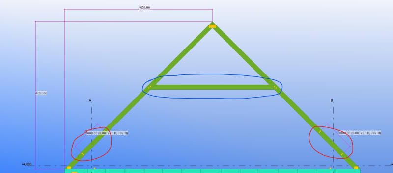
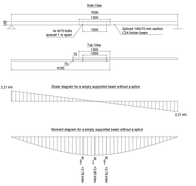
Perhaps you can help. I have this timber beam that has to be spliced since 7 m long elements are not available. I want to make a 1,3 m overlap, that has 2 bolts at each end of the splice so the bolt groups are spaced 1 m apart. Is this thing viable? I need to design the bolted connection and so I need the shear force acting on the bolts. Is shear due to moment here moment at the bolt location divided by the lever arm (1 m in this case)? Have you used this kind of splice before?
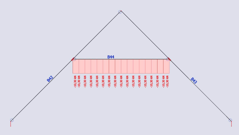
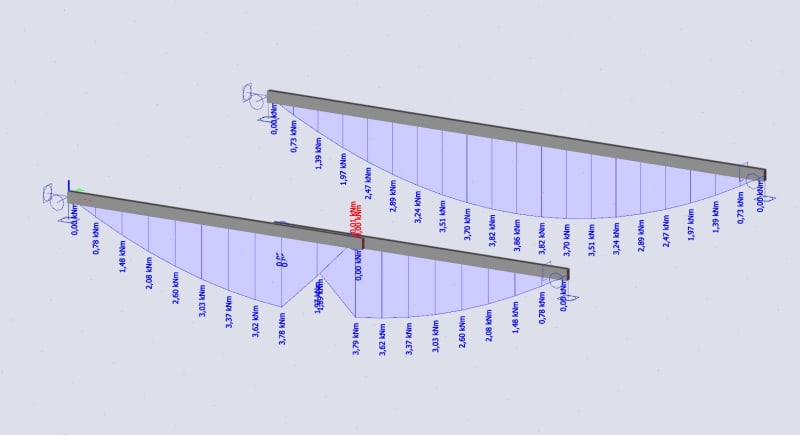
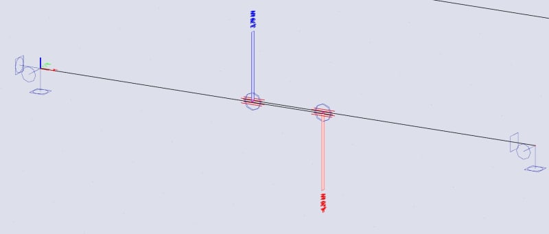
I also modeled something similar in SCIA Engineer with two timber beams and two very stiff 70 mm long steel rods (to represent the bolts) that would not deform too much under the load and the results seem to be pretty much confirm the case I was thinking about. The shear in one of the bolts is 3,79 kN and 4,2 kN in the other. Screenshots with moments in two beams (one spliced, on not), shear in beams and shear in the bolts.
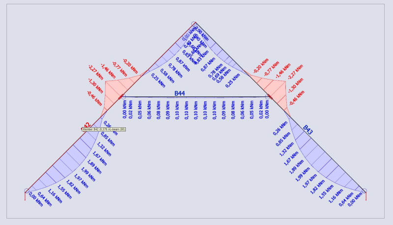
Moment diagrams:
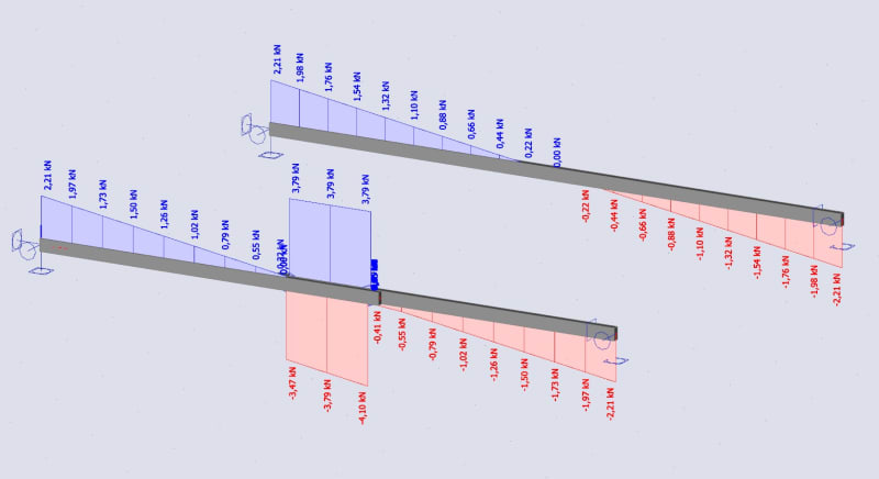
Shear diagram for beams:
Shear diagram for bolts:
Perhaps you can help. I have this timber beam that has to be spliced since 7 m long elements are not available. I want to make a 1,3 m overlap, that has 2 bolts at each end of the splice so the bolt groups are spaced 1 m apart. Is this thing viable? I need to design the bolted connection and so I need the shear force acting on the bolts. Is shear due to moment here moment at the bolt location divided by the lever arm (1 m in this case)? Have you used this kind of splice before?
I also modeled something similar in SCIA Engineer with two timber beams and two very stiff 70 mm long steel rods (to represent the bolts) that would not deform too much under the load and the results seem to be pretty much confirm the case I was thinking about. The shear in one of the bolts is 3,79 kN and 4,2 kN in the other. Screenshots with moments in two beams (one spliced, on not), shear in beams and shear in the bolts.
Moment diagrams:
Shear diagram for beams:
Shear diagram for bolts: