×
INTELLIGENT WORK FORUMS
FOR ENGINEERING PROFESSIONALS

Contact US

Log In

Come Join Us!

Are you an
Engineering professional?
Join Eng-Tips Forums!
  • Talk With Other Members
  • Be Notified Of Responses
    To Your Posts
  • Keyword Search
  • One-Click Access To Your
    Favorite Forums
  • Automated Signatures
    On Your Posts
  • Best Of All, It's Free!

*Eng-Tips's functionality depends on members receiving e-mail. By joining you are opting in to receive e-mail.

Posting Guidelines

Promoting, selling, recruiting, coursework and thesis posting is forbidden.

Students Click Here

Blade Helix definition?
2

Blade Helix definition?

Blade Helix definition?

(OP)
Can someone explain how are these blades defined? I am trying to model them in Catia but I am not sure what "lead" 6.000 RH" actually means and and where is the centre of helix twist.
Never seen this kind of dwg before (old dwg) so not sure if everything is defined here or there is some missing info...

RE: Blade Helix definition?

I would presume that the 6.000 is a pitch, similar to a thread call out.

= = = = = = = = = = = = = = = = = = = =
P.E. Metallurgy, consulting work welcomed

RE: Blade Helix definition?

CAUTION1. As I understand it... from friends who have designed complex sculpted compressor and turbine blades... most companies 'in-the-business' have developed and use proprietary CADD/CADM software for design/analysis [FEA/FEM] and manufacture... of these type parts.

Perhaps, this question should be resubmitted to engineering computer programs forum... for the specific 3D software You are using to model the compressor...

Regards, Wil Taylor
o Trust - But Verify!
o For those who believe, no proof is required; for those who cannot believe, no proof is possible. [variation, Stuart Chase]
o Unfortunately, in science what You 'believe' is irrelevant. ["Orion", HBA forum]
o Only fools and charlatans know everything and understand everything." -Anton Chekhov

RE: Blade Helix definition?

"lead" of a helix is how far the helix advances in one revolution, in this case 6.000 inches. So think of a radial line sweeping a helix, advancing (use the RH rule to figure out which direction the vane advances) on the central axis at 6.000 in/rev. Then the vane gets trimmed by two conical surfaces .720 in. apart. Now copy the vane formed 9 times equally spaced around the central axis.

RE: Blade Helix definition?

(OP)
What about position of helix centerline on the side view? I presumed its .440in or am I missing something?

RE: Blade Helix definition?

"Developed form of vane in direction of arrow X" confuses the hell out of me.

Section A-A cuts through two vanes, yet vanes are not shown with a hatch in (what seems to be) the section A-A view.

There is a section line B-B. Where is the B-B view?

One edge of each vane seems to be curved, but I don't see anything that defines the curvature.

The other edge doesn't seem to be shown.

It would help me if the direction of rotation or direction of flow were shown. Then I could make a better guess as to which way the vanes pitch.

RE: Blade Helix definition?

(OP)
B-B just shows fillets between blade and inner/outer walls...

RE: Blade Helix definition?

(OP)
Like Ed said I presumed its a thread callout and modeled it like helix with a 6in pitch. Position of a helix centerline is .440in dimension. This gives the closest result to the drawing but as you can see in image, the curvature of leading edge is not the same and point on leading edge tip doesnt end up on SECTION A-A line (part centerline) like in dwg...

RE: Blade Helix definition?

1. Do you have one of the parts?
2. Do you have access to the tooling?
The inlet is the bottom (or right-hand side depending on view)
I made centrifugal pumps for years. Our Catia drawings only showed the edges of the vanes, not the shape.
The shapes were defined by old-school methods on the tooling drawings.
After all we had to make core box inserts, then mold cores, place them into the mold, and then cast parts.
All we really cared about was being able to replicate the core box inserts, then we knew that the vanes would come out the same.
Considering that these are flat I am guessing that they are a very old design and made in a similar way.

= = = = = = = = = = = = = = = = = = = =
P.E. Metallurgy, consulting work welcomed

RE: Blade Helix definition?

I'm gonna back-up the last 2-submitter's here... and add/enhance a couple of aspects...

This component is more complex than it appears and may have embedded elements/practices intrinsic to this tiny [relatively small] extract of an original 'antique' component drawing. Often these antique drawings have lots secondary design elements that are filled with embedded proprietary specifications... and may be telegraphed within the PL or the NOTES.

Regardless, there its a whole world of 'reverse engineering' likely needed here. Among a few others that I'm aware of is...
MIL-HDBK-115 U.S. ARMY REVERSE ENGINEERING HANDBOOK (GUIDELINES AND PROCEDURES)

There are design elements likely to be defined more clearly in industry documents and texts related to centrifugal compressor design that could shed light on this 'basic drawing'.

ALSO... 'Hands-on' examination of a serviceable [or not] part could answer a lot of questions. I am unsure if this alloy permits it... but an X-ray/CT-scan-to-digital file might be useful.

Regards, Wil Taylor
o Trust - But Verify!
o For those who believe, no proof is required; for those who cannot believe, no proof is possible. [variation, Stuart Chase]
o Unfortunately, in science what You 'believe' is irrelevant. ["Orion", HBA forum]
o Only fools and charlatans know everything and understand everything." -Anton Chekhov

RE: Blade Helix definition?

(OP)
Almost all old drawings I came across, I was able to model the parts. Few I couldnt, had additional info called out somewhere in notes/PL (like Wil said). This one doesnt have any additional info anywhere, thats why I was sure it is fully defined and can be "easily" 3d modeled.
@ Ed 1.Yes, 2.No (but we wont resort to reverse engineering yet)

RE: Blade Helix definition?

I don't know how it's described in drafting terms but with airplane propellers a 36" pitch is how far the propeller would travel forward in one full revolution in an incompressible fluid.

I believe this factors in the twist of the blade which I assume keeps the aerodynamic load on the blade even from tip to hub.

My posts reflect my personal views and are not in any way endorsed or approved by any organization I'm professionally affiliated with.

RE: Blade Helix definition?

storm, I understand. Our issue was that if we had to make another pattern could we actually make the same parts.
Knowing the finished blade geometry isn't much help in that process, it is the tooling that is critical.

= = = = = = = = = = = = = = = = = = = =
P.E. Metallurgy, consulting work welcomed

RE: Blade Helix definition?

The end view showing curvature of the blades is due to the blade being truncated/trimmed by a conical surface. Do you see the 27 degree conical callout that defines the leading/trailing edges of the vanes?
Maybe you have modelled the 27 deg. conical trim already, and as you say, the curvature in the end view looks different - which view does the actual impeller most resemble, the drawing or your CAD model?

RE: Blade Helix definition?

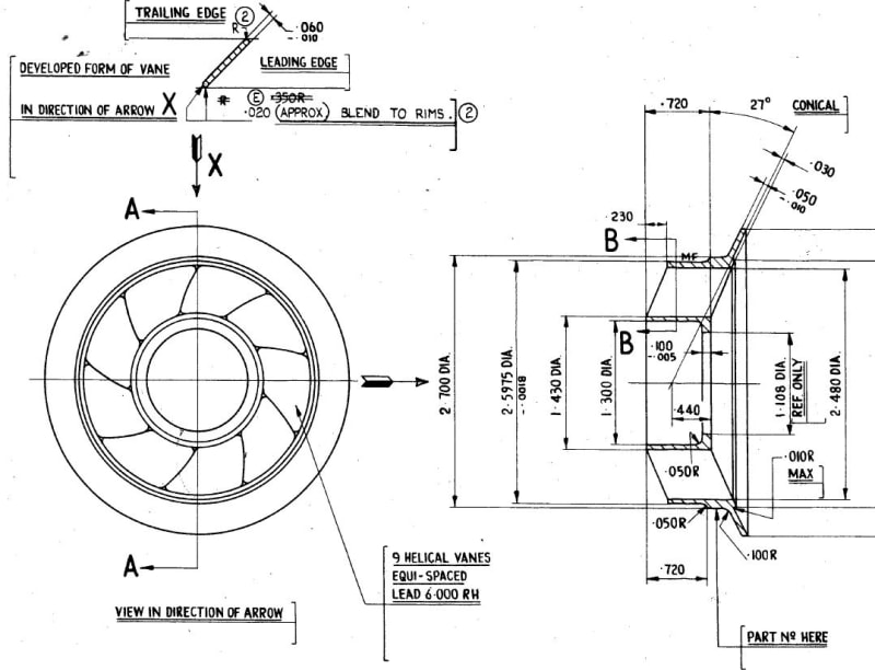
To show what I mean, with visuals generated in my 3d solid modelling program:

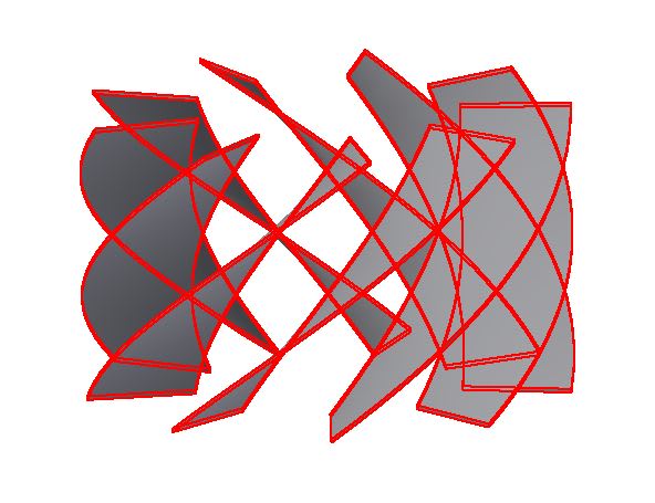
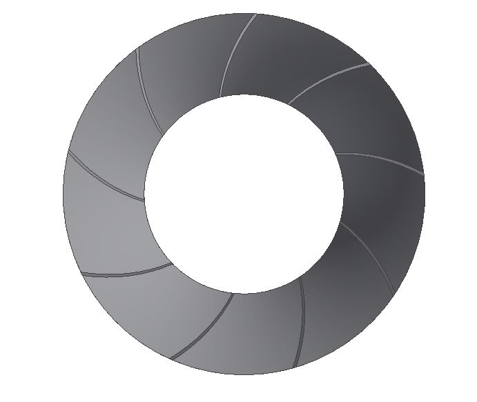
Here is an image of 9 developed screw flights: a horizontal rectangular shape swept through about 1/4 revolution on a 6.000 pitch helical path, and then circular patterned 9 times.


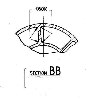
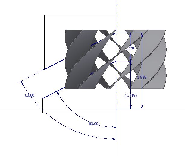
Next, I trimmed those flights with two triangular sections, making revolved cuts around the helix centerline, at 27 degrees to horizontal, or 63 degrees relative to the rotation axis of the helix, using the sketch shown below:


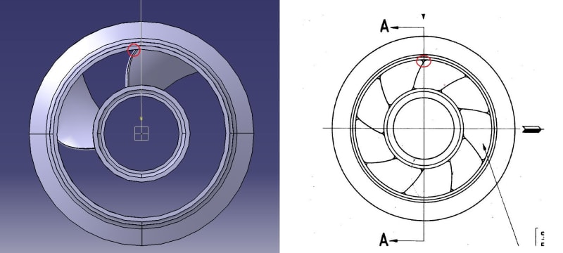
The result looks pretty close to what is shown in the drawings, see the end view of the trimmed impeller below (I have not modeled the i.d. and o.d. cylindrical surfaces nor the end conical flare):


It probably needs to be tweaked to get the vane section to the correct thickness. There will likely also be issues with how the "blend radii" at the i.d. and o.d. walls is accomplished in CAD, but then that's always the way it seems. Also, I didn't address Mint's concern about the side view of the developed vane, but would assume a horizontal section cut through a single vane would create a view similar to the drawing...or maybe not. Either way, I've wasted enough time and have other things to do now, and already deleted the cad file.

RE: Blade Helix definition?

(OP)
btrueblood thank you for the effort. I did the trim already and the actual impeller resembles drawing more than my 3D model but I am trying and tweaking it bit by bit with center of helix position etc. Unfortunately this is all playing and not really exact science as it should be :D

Red Flag This Post

Please let us know here why this post is inappropriate. Reasons such as off-topic, duplicates, flames, illegal, vulgar, or students posting their homework.

Red Flag Submitted

Thank you for helping keep Eng-Tips Forums free from inappropriate posts.
The Eng-Tips staff will check this out and take appropriate action.

Reply To This Thread

Posting in the Eng-Tips forums is a member-only feature.

Click Here to join Eng-Tips and talk with other members! Already a Member? Login


Resources

Low-Volume Rapid Injection Molding With 3D Printed Molds
Learn methods and guidelines for using stereolithography (SLA) 3D printed molds in the injection molding process to lower costs and lead time. Discover how this hybrid manufacturing process enables on-demand mold fabrication to quickly produce small batches of thermoplastic parts. Download Now
Design for Additive Manufacturing (DfAM)
Examine how the principles of DfAM upend many of the long-standing rules around manufacturability - allowing engineers and designers to place a part’s function at the center of their design considerations. Download Now
Taking Control of Engineering Documents
This ebook covers tips for creating and managing workflows, security best practices and protection of intellectual property, Cloud vs. on-premise software solutions, CAD file management, compliance, and more. Download Now

Close Box

Join Eng-Tips® Today!

Join your peers on the Internet's largest technical engineering professional community.
It's easy to join and it's free.

Here's Why Members Love Eng-Tips Forums:

Register now while it's still free!

Already a member? Close this window and log in.

Join Us             Close