2D problems in 3D
2D problems in 3D
(OP)
Hello everyone!
I've seen this thread: https://www.eng-tips.com/viewthread.cfm?qid=495987 and would like to expand the discussion to a more general case. This topic has been puzzling me for some time and seems to be quite common among FEA engineers. And yet I haven't found a comprehensive answer anywhere. Some FEA codes don't support 2D (plane stress/strain, axisymmetric) analyses, making it necessary to solve everything in 3D using solid (volume) elements. I wonder how one can model such problems properly so that the 3D analysis is equivalent to 2D simulation and the same results are obtained. Here are my thoughts:
1) PLANE STRESS (e.g. plate subjected to tension):
From what I've seen in the referenced thread, this one is realized sort of naturally if the structure is thin and loaded in its plane only. So boundary conditions can be arbitrary (just to avoid underconstraint) and there's no need to fix normal displacements (in the Z direction) for front and back faces of the structure. Is that right? Is there a need to use only 1 layer of elements in the thickness direction (Z) thus preventing the use of tetrahedral elements?
2) PLANE STRAIN (e.g. long pipe):
This one apparently requires fixing normal displacements for front and back faces of the structure but is it sufficient? Or should some additional boundary conditions be applied in the middle of the structure? I've heard about an approach in which front and back faces have equalized displacements and apart from that there's also a boundary condition applied in the middle (with normal displacements constrained). Does the number of element layers matter?
3) AXISYMMETRIC (e.g. pressure vessel):
Here I'm talking about taking a section (like 5 degrees or more) of a revolved model and applying such boundary conditions that it's equivalent to axisymmetric analysis. In such a case should I only constrain displacements normal to the faces of the cut (using local coordinate systems)? How does it differ from cyclic symmetry available in some FEA codes?
RE: 2D problems in 3D
You will not obtain the same results with solids and plane stress or plane strain 2D elements, because the 2D case is always stiffer than the 3D case.
For plates in tension or pressure vessels, the analysis can be done using shell elements. There is no need for volume elements, axisymmetry or plane strain assumptions.
Your questions are still interesting, if only for intellectual curiosity, and I hope somebody can answer them.
RE: 2D problems in 3D
I'm assuming that shells are not considered here, especially since some FEA programs don't have them as well and 3D solid (volume) elements have to be used. What's more, often only tetrahedral elements are supported and then there's a question whether more than 1 layer of elements can be used for such "2D in 3D" analyses, as mentioned above.
RE: 2D problems in 3D
I made some tests with 3D analyses of 2D problems and here are the conclusions:
PLANE STRESS:
- some out-of-plane stress can be observed regardless of boundary conditions
- it’s best (results in lowest out-of-plane stress) to avoid fixing the front and back faces in the normal direction (Poisson’s effect - better fix one vertex in this direction instead)
- it’s not necessary to use a single layer of elements in the thickness direction
PLANE STRAIN:
- out-of-plane strain is zero
- it’s necessary to fix the front and back faces in the normal direction
- it’s not necessary to use a single layer of elements in the thickness direction or the approach mentioned by the OP (equalizing displacements for the front and back faces and applying symmetry boundary condition in the middle)
AXISYMMETRIC:
- it’s sufficient to fix displacements in the normal direction for the faces of the cut - local coordinates are needed if the cut is not aligned with global axes due to a segment narrower than 90 degrees being analyzed (cylindrical coordinate system is recommended - easiest to use)
- it’s not necessary to use a single layer of elements
- cyclic symmetry may also be used (take a closer look at the boundary conditions - cyclic symmetry itself doesn’t prevent the model from rotating about the axis of symmetry)
I will appreciate your comments, especially if you know about or encounter any exceptions where different approach than suggested here should be used (I tried to make this as general as possible but it’s possible that there are some specific cases requiring a different treatment).
RE: 2D problems in 3D
I'm surprised your "plane strain" modelling (as I read it, fixing the out-of-plane freedom) works. unless your loading was limited to in-plane. These constraints didn't react load ?
I like the conclusion that you can use 1 element through the thickness. This means that "someone" can create a 2D stress or strain 3D element.
"Hoffen wir mal, dass alles gut geht !"
General Paulus, Nov 1942, outside Stalingrad after the launch of Operation Uranus.
RE: 2D problems in 3D
When it comes to plane strain, I checked two cases - a thick pipe subjected to internal pressure and another thick pipe subjected to heating (higher temperature inside, lower outside). The stresses were in very good agreement with theoretical solutions. Since plane strain (unlike so-called generalized plane strain) assumes restricted deformation (but possible stress) in the thickness direction and loading acting along the whole thickness, this approach seems to be valid. Or did I miss something ?
RE: 2D problems in 3D
I don't think you'd get the same result if you have a plate in bending.
Your pipe tet also I think explains why 1 element through the thickness is adequate ... no bending. I wonder hoe thick pipe walls need to be to generate significant secondary bending ?
"Hoffen wir mal, dass alles gut geht !"
General Paulus, Nov 1942, outside Stalingrad after the launch of Operation Uranus.
RE: 2D problems in 3D
By plate in bending do you mean plane strain model of a long plate with length defined as a thickness of plane strain elements ? I can check it but I wouldn’t expect symmetry boundary conditions applied to the front and back faces to change the results in such a case.
Perhaps I should share some screenshots to make it clear how the models looked like (especially when it comes to boundary conditions).
RE: 2D problems in 3D
I have thought about the poisson effects in the thickness direction ... with tension in the axial and hoop directions, there'd be compression (thinning) in the thickness direction. So typically a plane stress problem with 3D strain. To make it a 2D problem you need very thin walls, to constrain the thickness displacement (2D strain, = 3D stress)
"Hoffen wir mal, dass alles gut geht !"
General Paulus, Nov 1942, outside Stalingrad after the launch of Operation Uranus.
RE: 2D problems in 3D
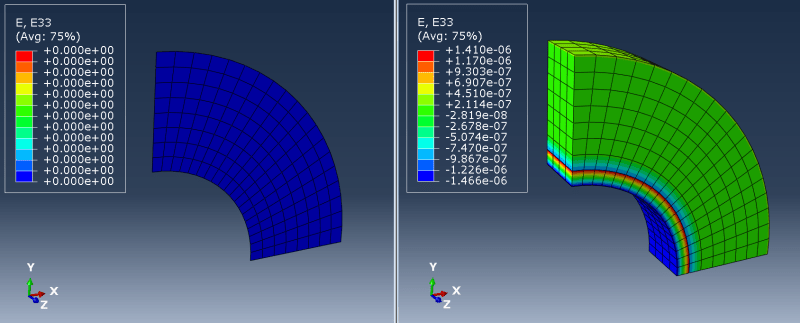
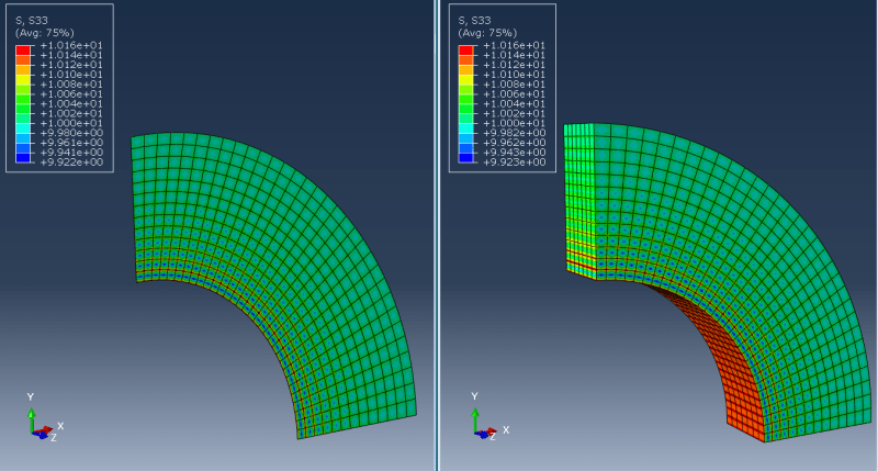
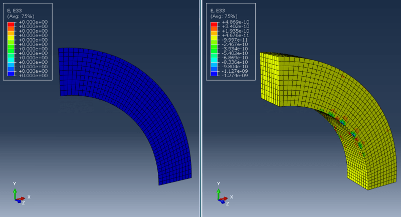
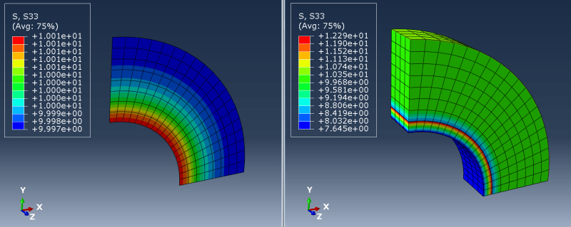
- out-of-plane stress:
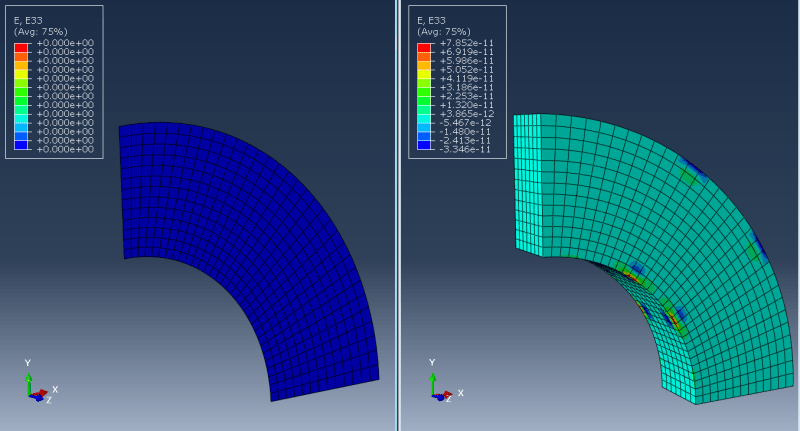
- out-of-plane strain:
In a 3D analysis, the front and back faces were fixed in the normal direction but the same result was obtained with that advanced approach mentioned before (equalized displacements for the front and back faces plus symmetry in the middle). Also, a single layer of elements gave the same results.
As you can see, out-of-plane strain is present in a 3D analysis but it's almost zero. Only the distribution of the out-of-plane stress seems to be affected but away from that inner surface, the values are around 10 MPa (like in a 2D analysis).
RE: 2D problems in 3D
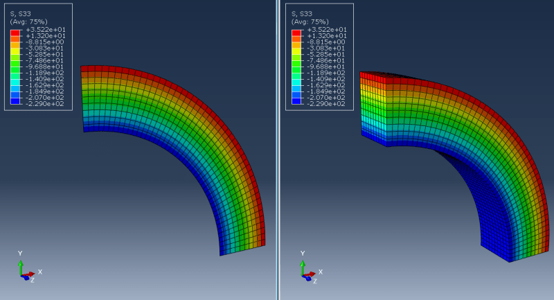
And for the second analyzed plane strain case (pipe subjected to heating):
As you can see, the agreement is very good.