Unstiffened RHS mitre joint
(OP)
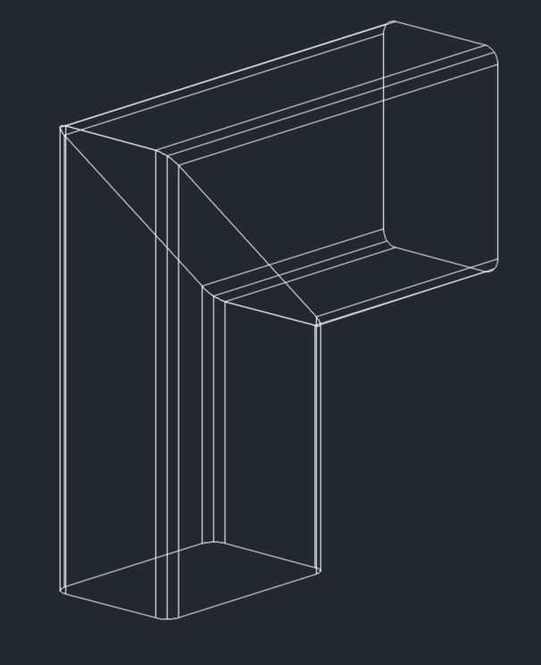
I am trying to model the plastic collapse load for an unstiffened RHS mitre joint using Strand7 (unstiffened in the sense that there is no diagonal end plate welded between the two RHS sections - the two RHSs are simply mitre cut and butt welded together and the joint is hollow all the way through).
I just want to check that my general approach is OK.
The section is a 150x100x5.0 RHS, fy = 450 MPa, fu = 500 MPa. For reference, the plastic section capacity is 52 kNm.
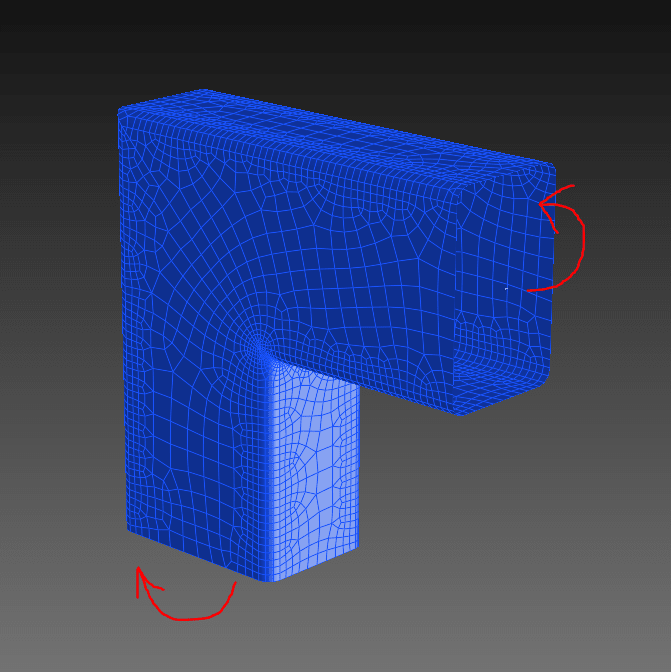
The model consists of 8-node curved plate elements (mostly), although the auto-mesh feature occasionally includes some 6-node triangles here and there. Meshing is more refined around the inside corners where the stress tends to concentrate. The straight portion away from the joint is about 150 mm long, equal to the height of the section. I've used a multi-node link at each end, one with fixed boundary conditions, and the other set to rotate 0.05 degrees about the major axis so that the joint is opening.

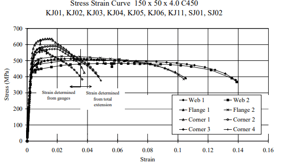
The stress-strain curve is shown below:
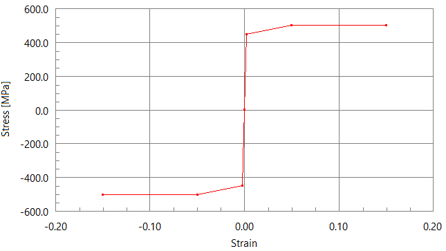
The model runs fine up until the 8th time step (i.e. for an imposed rotation of 8 x 0.05 = 0.40 degrees), at which point it struggles to converge on a solution. My main reference for this type of joint says that the capacity should reach approximately 50% of the section capacity, i.e. 50% x 52 kNm ~ 26 kNm.
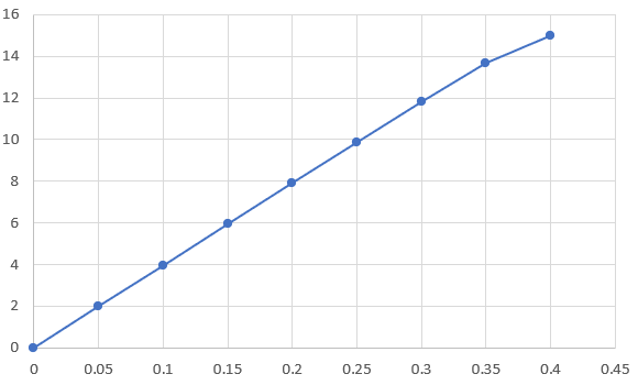
However, you can see on the graph below (bending moment [kNm] vs rotation [degrees]) that it doesn't seem to approach any sort of collapse mechanism, there is only a hint of non-linear behaviour as the rotation approaches 0.4 degrees.
Below is showing the yielded areas at rotations of 0.30, 0.35 and 0.40 (not converged) degrees.
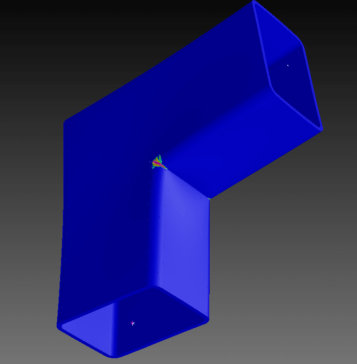
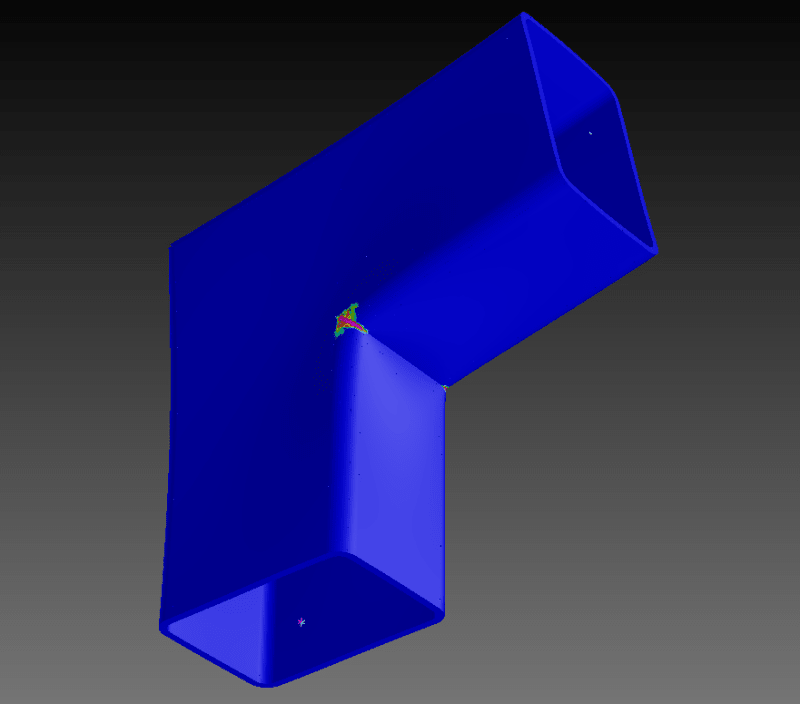
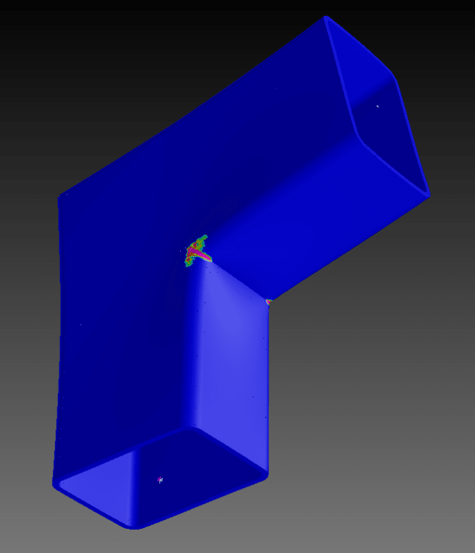
This seems to confirm that the collapse mechanism is not even close to being reached. The yielding is only occurring locally around the corners of the joint.
There are no odd stress concentrations or deformations occurring around the multi-node links, so I'm confident this isn't the issue.
Is it simply a case of the 'load' step being too large? Should I just set this to be smaller and leave it to run for longer? Any other suggestions?
I just want to check that my general approach is OK.
The section is a 150x100x5.0 RHS, fy = 450 MPa, fu = 500 MPa. For reference, the plastic section capacity is 52 kNm.
The model consists of 8-node curved plate elements (mostly), although the auto-mesh feature occasionally includes some 6-node triangles here and there. Meshing is more refined around the inside corners where the stress tends to concentrate. The straight portion away from the joint is about 150 mm long, equal to the height of the section. I've used a multi-node link at each end, one with fixed boundary conditions, and the other set to rotate 0.05 degrees about the major axis so that the joint is opening.


The stress-strain curve is shown below:

The model runs fine up until the 8th time step (i.e. for an imposed rotation of 8 x 0.05 = 0.40 degrees), at which point it struggles to converge on a solution. My main reference for this type of joint says that the capacity should reach approximately 50% of the section capacity, i.e. 50% x 52 kNm ~ 26 kNm.
However, you can see on the graph below (bending moment [kNm] vs rotation [degrees]) that it doesn't seem to approach any sort of collapse mechanism, there is only a hint of non-linear behaviour as the rotation approaches 0.4 degrees.

Below is showing the yielded areas at rotations of 0.30, 0.35 and 0.40 (not converged) degrees.


This seems to confirm that the collapse mechanism is not even close to being reached. The yielding is only occurring locally around the corners of the joint.
There are no odd stress concentrations or deformations occurring around the multi-node links, so I'm confident this isn't the issue.
Is it simply a case of the 'load' step being too large? Should I just set this to be smaller and leave it to run for longer? Any other suggestions?
RE: Unstiffened RHS mitre joint
have you tests to compare to ?
"Hoffen wir mal, dass alles gut geht !"
General Paulus, Nov 1942, outside Stalingrad after the launch of Operation Uranus.
RE: Unstiffened RHS mitre joint
-----*****-----
So strange to see the singularity approaching while the entire planet is rapidly turning into a hellscape. -John Coates
-Dik
RE: Unstiffened RHS mitre joint
SWComposites - you're correct, it is a sharp point, particularly at that concave portion at the inside of the joint, which is where I am getting the large stress concentration. I hadn't really considered that as a problem before, but this is something I might look into. Do you know whether the nonlinear material in my model would help to 'relieve' that stress concentration in the model and avoid this as an issue?
dik - the reference I'm considering is one of the Australian Steel Institute design guides (which I don't have in front of me unfortunately). I think they go into pretty good detail about how this joint collapses, which is where they derive the ~50% number from. For reference, with a stiffener plate welded between, I recall that the capacity is close to 100% (if not 100%).
RE: Unstiffened RHS mitre joint
further, how are you accounting for the different properties of the weld material?
RE: Unstiffened RHS mitre joint
To learn how to model welds I think you need a set of test data to info how to build the model. "fussing" over the profile of the weld will only beguile you into believing the results of the FEM. I would expect that you can get a long way modelling with plates, but I would expect that the weld could be modelled by a CBUSH (well, that's the NASTRAN element for some sort of spring ... STRAND7 has never impressed me, from what I've read about it here). And to get anywhere near right, you'll need to run material (and maybe geometry) non-linear.
"Hoffen wir mal, dass alles gut geht !"
General Paulus, Nov 1942, outside Stalingrad after the launch of Operation Uranus.
RE: Unstiffened RHS mitre joint
I am running material and geometry nonlinearity.
RE: Unstiffened RHS mitre joint
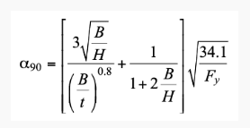
For your info, I have found a reference for you:
https://steeltubeinstitute.org/resources/hss-knee-...
For this specific case, we would get alpha_90 = 0.471.
RE: Unstiffened RHS mitre joint
-----*****-----
So strange to see the singularity approaching while the entire planet is rapidly turning into a hellscape. -John Coates
-Dik
RE: Unstiffened RHS mitre joint
How is geometric non-linearity modelled: is it a von Karman type non-linearity (quadratic order strains for the kinematics, moderate rotations), or a finite strain and finite displacement formulation that solves the system based on deformed geometry? Is the geometrical non-linearity non-locking, i.e., is the formulation such that no membrane locking or shear locking can occur?
What is the solver? Is it a Newton-Raphson or modified Newton-Raphson solver with force control (those do not converge for non-monotonic stress-strain or load-displacement behavior), or an arc-length method with displacement control (should converge for almost any type of problem with small enough displacement increments and enough iterations per displacement increment), or something else?
How is the material modelling performed? The stress-strain curve you show is not very realistic and seems to be based on some rough zero-hardening idealization found in a code.
Non-linear finite element analysis is really quite complicated, and many softwares with NL FEA do not offer a robust and reliable procedure for it. Quite a lot can go wrong, and rarely will customer support admit to the software being unreliable. I am not familiar with Strand7, but I am quite certain that at least ABAQUS and ANSYS can solve this problem and both have user manuals and customer support which will not actively try to hide the details (elements, locking behaviour, kinematics, material modelling, solvers etc.) of their product.
RE: Unstiffened RHS mitre joint
-----*****-----
So strange to see the singularity approaching while the entire planet is rapidly turning into a hellscape. -John Coates
-Dik
RE: Unstiffened RHS mitre joint
@centondolar - I can't answer all your questions, but I'll try. I believe the plates are Kirchoff; I have since removed the geometric nonlinearity as it was slowing down the solver and I don't think it's necessarily relevant in this case; arc-length method; you're correct about the stress-strain curve, this isn't necessarily realistic.
I have since simplified things a bit. I split the model into 1/4 of the previous and included symmetry conditions, removed the geometric nonlinearity, and made the mesh a bit coarser. This seems to get the solver to work in a more reasonable time.
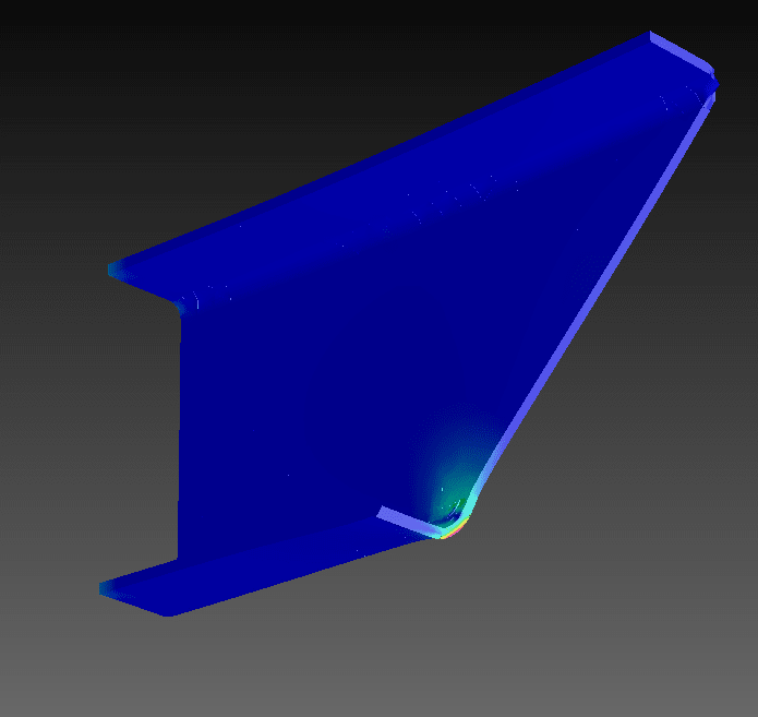
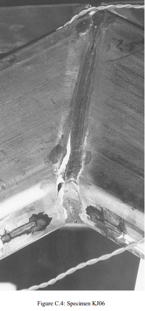
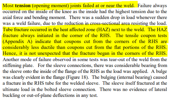
Doing some more reading on the topic (e.g. tests by Wilkinson and Hancock ca. 1998, there's plenty of papers out there), joints of this type tend to fail by tearing of the tube or failure of the weld in the highly stressed corner shown above.
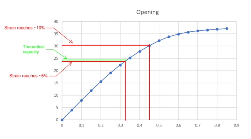
This occurs well before a complete collapse mechanism is able to form. My results tend to show this as well - below you can see that when the strain in the tube starts to exceed about 5%, this is where the theoretical capacity occurs.
Anyway, I think I'm done with this little exercise for now. Thanks for the comments everyone.
RE: Unstiffened RHS mitre joint
Interesting excerpts from one of the papers I read - 'Tests of knee joints in cold-formed rectangular hollow sections' by Wilkinson and Hancock 1998.
(My highlights added for emphasis)
Fracture at the corner of the RHS occurs at around 5% strain.