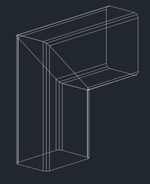
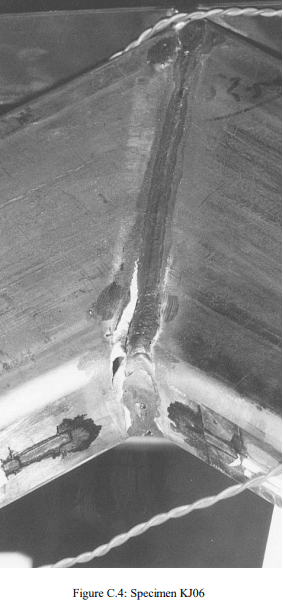
I am trying to model the plastic collapse load for an unstiffened RHS mitre joint using Strand7 (unstiffened in the sense that there is no diagonal end plate welded between the two RHS sections - the two RHSs are simply mitre cut and butt welded together and the joint is hollow all the way through).
I just want to check that my general approach is OK.
The section is a 150x100x5.0 RHS, fy = 450 MPa, fu = 500 MPa. For reference, the plastic section capacity is 52 kNm.
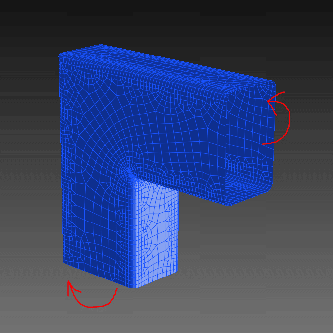
The model consists of 8-node curved plate elements (mostly), although the auto-mesh feature occasionally includes some 6-node triangles here and there. Meshing is more refined around the inside corners where the stress tends to concentrate. The straight portion away from the joint is about 150 mm long, equal to the height of the section. I've used a multi-node link at each end, one with fixed boundary conditions, and the other set to rotate 0.05 degrees about the major axis so that the joint is opening.

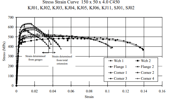
The stress-strain curve is shown below:
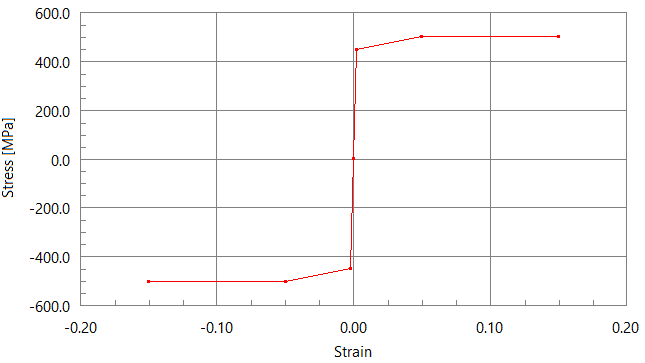
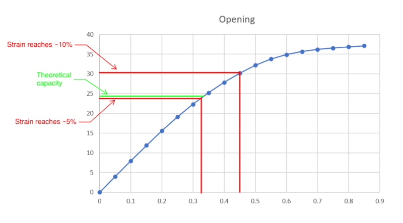
The model runs fine up until the 8th time step (i.e. for an imposed rotation of 8 x 0.05 = 0.40 degrees), at which point it struggles to converge on a solution. My main reference for this type of joint says that the capacity should reach approximately 50% of the section capacity, i.e. 50% x 52 kNm ~ 26 kNm.
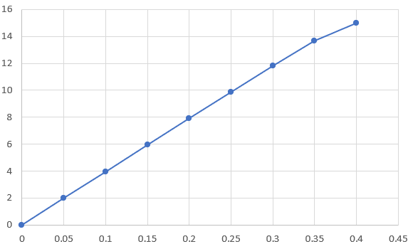
However, you can see on the graph below (bending moment [kNm] vs rotation [degrees]) that it doesn't seem to approach any sort of collapse mechanism, there is only a hint of non-linear behaviour as the rotation approaches 0.4 degrees.
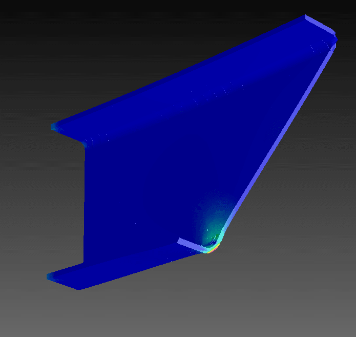
Below is showing the yielded areas at rotations of 0.30, 0.35 and 0.40 (not converged) degrees.
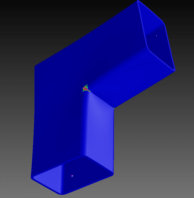
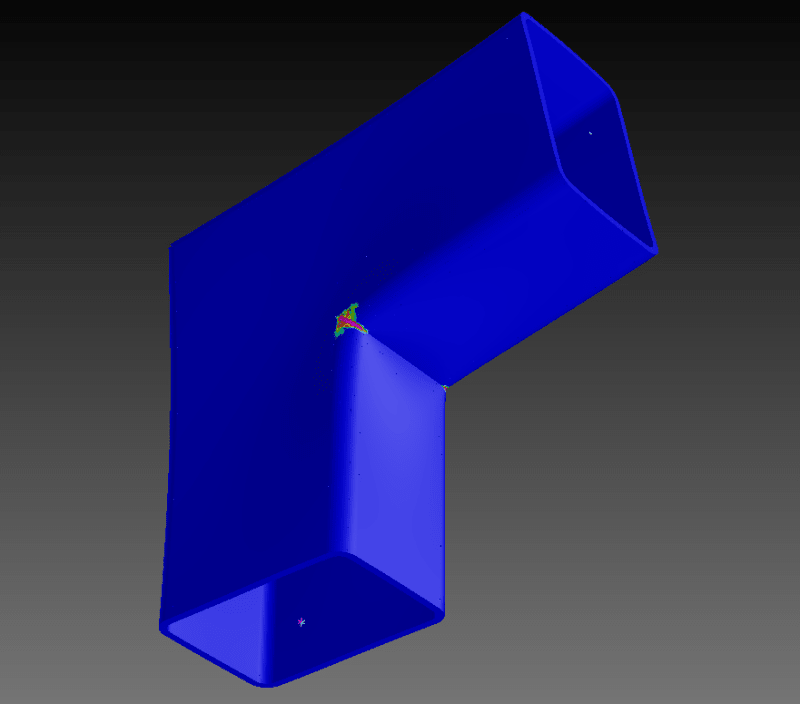
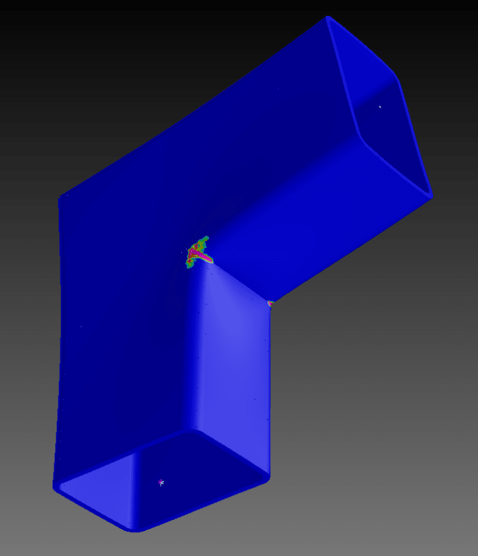
This seems to confirm that the collapse mechanism is not even close to being reached. The yielding is only occurring locally around the corners of the joint.
There are no odd stress concentrations or deformations occurring around the multi-node links, so I'm confident this isn't the issue.
Is it simply a case of the 'load' step being too large? Should I just set this to be smaller and leave it to run for longer? Any other suggestions?
I just want to check that my general approach is OK.
The section is a 150x100x5.0 RHS, fy = 450 MPa, fu = 500 MPa. For reference, the plastic section capacity is 52 kNm.
The model consists of 8-node curved plate elements (mostly), although the auto-mesh feature occasionally includes some 6-node triangles here and there. Meshing is more refined around the inside corners where the stress tends to concentrate. The straight portion away from the joint is about 150 mm long, equal to the height of the section. I've used a multi-node link at each end, one with fixed boundary conditions, and the other set to rotate 0.05 degrees about the major axis so that the joint is opening.
The stress-strain curve is shown below:
The model runs fine up until the 8th time step (i.e. for an imposed rotation of 8 x 0.05 = 0.40 degrees), at which point it struggles to converge on a solution. My main reference for this type of joint says that the capacity should reach approximately 50% of the section capacity, i.e. 50% x 52 kNm ~ 26 kNm.
However, you can see on the graph below (bending moment [kNm] vs rotation [degrees]) that it doesn't seem to approach any sort of collapse mechanism, there is only a hint of non-linear behaviour as the rotation approaches 0.4 degrees.
Below is showing the yielded areas at rotations of 0.30, 0.35 and 0.40 (not converged) degrees.
This seems to confirm that the collapse mechanism is not even close to being reached. The yielding is only occurring locally around the corners of the joint.
There are no odd stress concentrations or deformations occurring around the multi-node links, so I'm confident this isn't the issue.
Is it simply a case of the 'load' step being too large? Should I just set this to be smaller and leave it to run for longer? Any other suggestions?