Testing equipment for measuring powerline ground impedance
(OP)
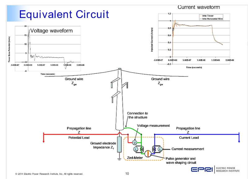
Anyone here has experience with measuring ground resistance of tower/ structure footing? What testing tools are typically used by utilities to determine the footing resistance? We recently had few back flashovers on our power lines, so we are doing the root cause analysis and starting with the structure footing resistance.
RE: Testing equipment for measuring powerline ground impedance
If you have a steel pole or tower grounded through with the pole or to a foundation, things are complicated. You can't fit the clamp of a simple clamp type ground tester around the connections to ground (the whole pole or tower base). You normally can't disconnect the tower or pole from the shield, so a fall of potential test won't work because you will be including the multigrounded shield wire in the measurement. There are specialized test sets to make the measurements. See https://www.youtube.com/watch?v=R_exTjDshM4 for example.
RE: Testing equipment for measuring powerline ground impedance
I wonder what Quebec Hydro is using (?) but I did see among the evaluators, my current and former suppliers listed for their contributions during evaluation. Hydro One and Manitoba Hydro) Duke also uses it.
https://vdocuments.net/zed-meter-basic-operation.h...
Fundamentally it measures V(t)= I(t)R + L dI(t)/dt then the ratio of V(t)/I(t) is impedance Z(t) which may be converted to frequency domain. The time constant for inductive wire is Tau=L/R (63% of target) then there is an air ionization time that depends on path length and capacitance. Lightning tracers are a chain reaction of PD to ionize the air with low resistance then the follow-on return arc goes at the speed of light and ultra-high current limited only by the tower resistance which might be around 5 ohms.
I recall long wire is about 1 uH/m.
This test measures the impedance before the next tower ground can react due to the rise time of the pulse is shorter than the T=L/R.
The standard method relies on the characteristic impedance of ~ 100 m cable over soil which has some distributed coupling capacitance to ground such that the impedance is measured for at least the 300 ns flat portion of pulse before the reflected wave occurs from the cable end. (although it could have been terminated to prevent that) 200m/2e8m/s = 1e-6 s or 1000 nano-nano seconds. ;)
Tony Stewart
EE since 1975
retired but consults on request.