azchris
Electrical
- Jul 13, 2022
- 2
thread240-431670
Regarding the previous (now closed) post:
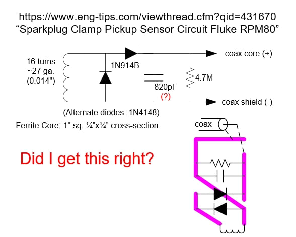
"Sparkplug Clamp Pickup Sensor Circuit Fluke RPM80"
I found the thread discussing internals of the Fluke RPM80 pickup and there are a lot of photos but I didn't see an actual schematic.
I drew up what I think is the schematic but I wanted to confirm since I may have misinterpreted the photos
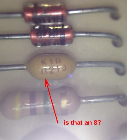
Also, I am not sure I correctly read the value of the Capacitor (does it say K1G / 821J ? I'm not sure I read the first digit (8?) correctly).
So I was hoping the original author of that post (MRSSPOCK) could comment... thanks!
Regarding the previous (now closed) post:
"Sparkplug Clamp Pickup Sensor Circuit Fluke RPM80"
I found the thread discussing internals of the Fluke RPM80 pickup and there are a lot of photos but I didn't see an actual schematic.
I drew up what I think is the schematic but I wanted to confirm since I may have misinterpreted the photos
Also, I am not sure I correctly read the value of the Capacitor (does it say K1G / 821J ? I'm not sure I read the first digit (8?) correctly).
So I was hoping the original author of that post (MRSSPOCK) could comment... thanks!