×
INTELLIGENT WORK FORUMS
FOR ENGINEERING PROFESSIONALS

Contact US

Log In

Come Join Us!

Are you an
Engineering professional?
Join Eng-Tips Forums!
  • Talk With Other Members
  • Be Notified Of Responses
    To Your Posts
  • Keyword Search
  • One-Click Access To Your
    Favorite Forums
  • Automated Signatures
    On Your Posts
  • Best Of All, It's Free!

*Eng-Tips's functionality depends on members receiving e-mail. By joining you are opting in to receive e-mail.

Posting Guidelines

Promoting, selling, recruiting, coursework and thesis posting is forbidden.

Students Click Here

Zero-Cross detect circuit

Zero-Cross detect circuit

Zero-Cross detect circuit

(OP)
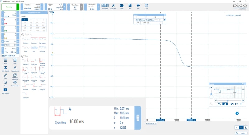
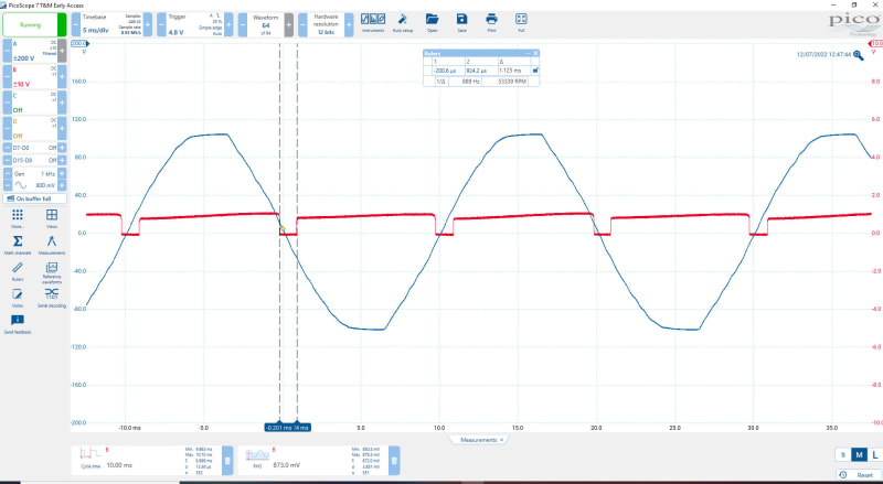
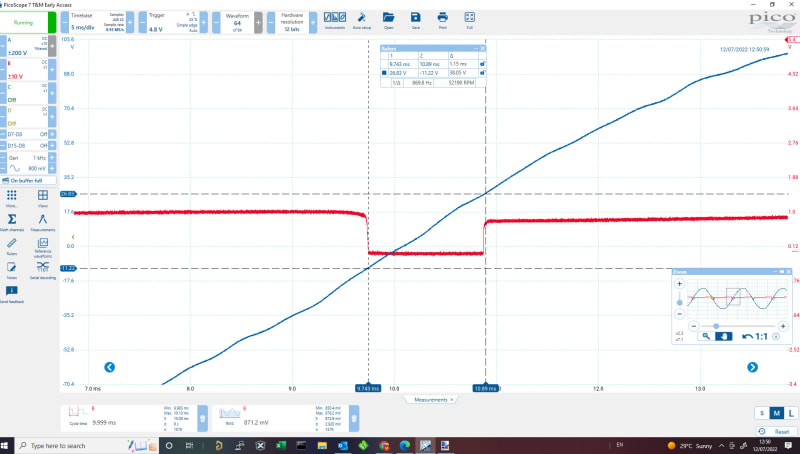
I am using a Triac dimmer for dimming an LED (dimmable) lamp. The zero-cross detector is from a simple transistor on the secondary of the transformer (before smoothing). All works fine except that the LED flickers a bit in the low range. Analyzing on the scope the zero-cross pulses vary in the range of 50us between cycles and this is enough to vary the brightness of the LED lamp at the low voltage ranges.
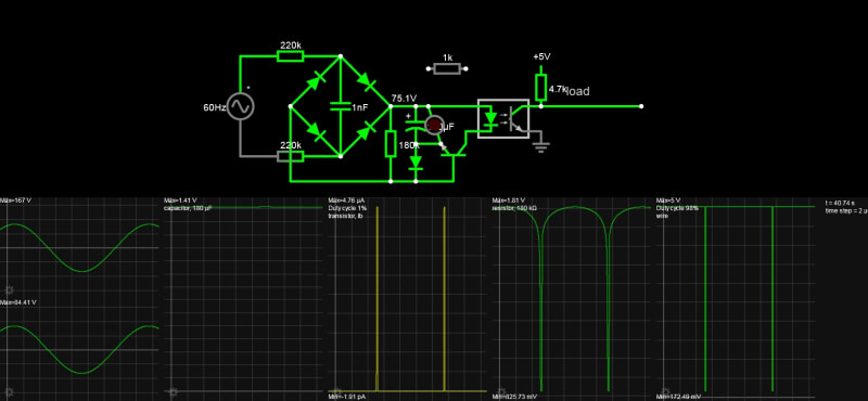
I have tried this circuit - https://cdn.hackaday.io/files/1597066832861504/Sim... but still got same error in the pulses.
With incandescent lamp this problem is not visible as the lamp has not enough time to turn off from cycle to cycle.

Is this normal to have such error on mains frequency? And is there any way to solve this?

RE: Zero-Cross detect circuit

What's your circuit?

The mains frequency doesn't change at all. However there could easily be harmonic distortion on it. Have you looked at it with a scope?
BEWARE looking at the mains with a mains powered scope is non-trivial. Read up on it before attempting it.

Keith Cress
kcress - http://www.flaminsystems.com

RE: Zero-Cross detect circuit

(OP)


Here is a test using this circuit - https://cdn.hackaday.io/files/1597066832861504/Sim...
I have increased the input capacitor to 10nF and added a dual coil filter on the input but still getting around 50us between cycles. I don't have an isolated probe to show the input sinewave at the same time.
I do have harmonic distortion from the Inverter Air-conditioner but with the added filtering it is not making much difference.

The scope image shows the cycle time which varies from 9.71ms to 10.03ms. The main image shows the falling edge of the second pulse which varies continuously between the rulers.

RE: Zero-Cross detect circuit

(OP)


Ok managed to capture input sinewave (through 3 series 100k resistors and measuring on the middle one = 1/3 voltage) and output pulses at the same time.
Sinewave does not look very good so probably its the harmonics that are messing with the timing.
Zooming on the pulse rise/fall time the variation is happening in sync with the variations of the input sinewave. Even setting probe with 200Hz filter it is still not stable enough.

RE: Zero-Cross detect circuit

in my simulations, the duty cycle was not narrow enough 12%. To improve this greatly to 1 to 2% and thus reduce low-level Triac phase and jitter;

1. Change load R2 from 22k to 100k . This is essential to cut the duty cycle in half. This may be enough but for more reduction in duty cycle keep reading.
2. Put a RED LED across C1. This reduces the width of the charge pulse and also the Cap voltage to about <=1.5V with low charge current and not illuminated but also reduces the ripple and cuts the base current duty cycle to 1% That may work.
3. Pulse spreading then occurs to 2% with a medium hFE 2N3904. A high hFE 2N5088 or PN2222A will boost the current but not lower the voltage much since the D.F. is now 1% The current limiting resistor, R4 is now redundant and may be bypassed as the LED limits the Opto diode current.

This should result in 20 us pulses.

I prefer to use an XOR gate from a line freq square wave with one leg delayed by T=RC with leading-edge in sync, but you may want a symmetric pulse.

https://tinyurl.com/28twe9w2


Red Flag This Post

Please let us know here why this post is inappropriate. Reasons such as off-topic, duplicates, flames, illegal, vulgar, or students posting their homework.

Red Flag Submitted

Thank you for helping keep Eng-Tips Forums free from inappropriate posts.
The Eng-Tips staff will check this out and take appropriate action.

Reply To This Thread

Posting in the Eng-Tips forums is a member-only feature.

Click Here to join Eng-Tips and talk with other members! Already a Member? Login


Resources

Low-Volume Rapid Injection Molding With 3D Printed Molds
Learn methods and guidelines for using stereolithography (SLA) 3D printed molds in the injection molding process to lower costs and lead time. Discover how this hybrid manufacturing process enables on-demand mold fabrication to quickly produce small batches of thermoplastic parts. Download Now
Design for Additive Manufacturing (DfAM)
Examine how the principles of DfAM upend many of the long-standing rules around manufacturability - allowing engineers and designers to place a part’s function at the center of their design considerations. Download Now
Taking Control of Engineering Documents
This ebook covers tips for creating and managing workflows, security best practices and protection of intellectual property, Cloud vs. on-premise software solutions, CAD file management, compliance, and more. Download Now

Close Box

Join Eng-Tips® Today!

Join your peers on the Internet's largest technical engineering professional community.
It's easy to join and it's free.

Here's Why Members Love Eng-Tips Forums:

Register now while it's still free!

Already a member? Close this window and log in.

Join Us             Close