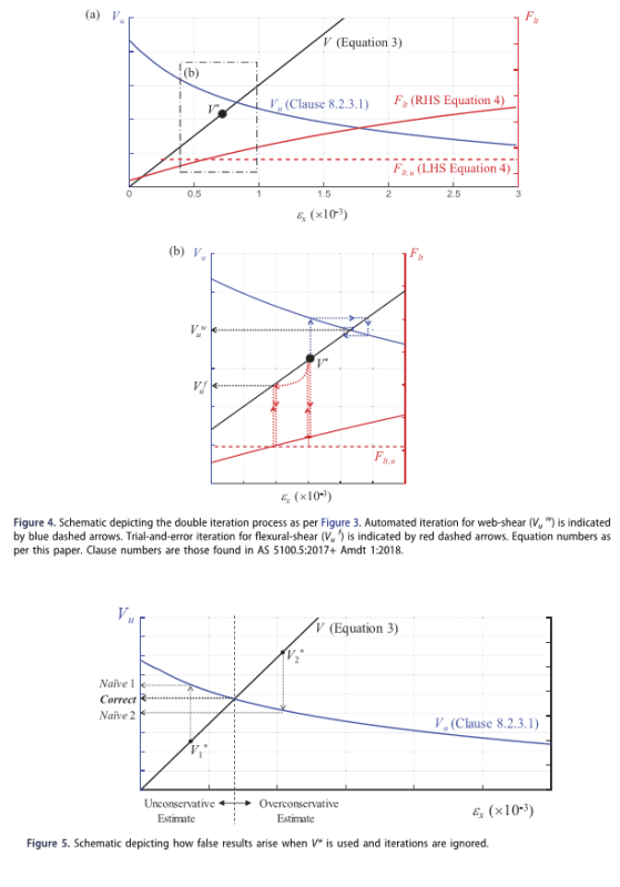
Recommendation to scale factored action effects to determine shear capacity for load rating
(OP)
A few articles have been published recommending the use of a scaled load (action) effects to determine ultimate shear capacity for use with load rating to AS 5100.7. It is not clear from these articles why it is necessary to do that. Doing so will result in the strengths being different for design and load rating of a new bridge for a same vehicle (i.e. design vehicle is the same as nominated rating vehicle). Any input to this will be much appreciated.
RE: Recommendation to scale factored action effects to determine shear capacity for load rating
At the moment I'm not sure what is being suggested.
Doug Jenkins
Interactive Design Services
http://newtonexcelbach.wordpress.com/
RE: Recommendation to scale factored action effects to determine shear capacity for load rating
https://doi.org/10.1080/13287982.2019.1664207
RE: Recommendation to scale factored action effects to determine shear capacity for load rating
Basically, increasing the bending moment and shear force, like is done in load rating, reduces the shear capacity in MCFT. Load rating requires iteration in the new code whereas the old shear method just required one-step comparison between nominal shear force and known shear capacity.
https://www.eng-tips.com/viewthread.cfm?qid=447856
RE: Recommendation to scale factored action effects to determine shear capacity for load rating
Response to the first comment.
The general equation for load rating can be shown as
RF = (phiV_u - V*_PL) / V*_LL
V_u = function of (V*,M*,T*) for example
MCFT requires consistency between the shear capacity and the applied load.
For a moving vehicle moving along a bridge, the combination of V*,M* and T* can be calculated for the bridge vehicle system at a key section for each incremental movement, say 0.1m for example.
The vehicle is moved along the bridge and the values of (phiV_u, M*, T*,V*) are calculated for all the steps. The RF of sections are calculated for every step and the smallest is chosen to be the RF of the bridge.
In accordance with the MCFT, the capacity used is consistent with the applied loading. No iteration is required.
The recommended approach in the article uses a set of factored load M*,V*,T* of the vehicle and the bridge system with the vehicle located to give the worse effects. A set of coefficients are calculated as:
eta_M = M*/V*, eta_T = T*/V*, and V is increased progressively starting from 0. M and T are calculated as M=eta_M V, T=eta_T V, and V_u is calculated from M,V and T. The iteration is continued until V=V_u. The V_u thus determined is not the V_u determined using direct calculation (which is the current practice). Interpreting in accordance with MCFT, the approach resulted in a V_u (proposed) that is for a scaled loading where the entire loading (both PL and LL) is scaled by a factor V_u(proposed)/V*. This capacity is not consistent with applied loading of the bridge vehicle system.
RE: Recommendation to scale factored action effects to determine shear capacity for load rating
Response to your second comment.
I was referring to a new bridge and using the same vehicle,i.e. design_vehicle = rating_vehicle, and the use of the same set of design standards. The general expectation is V_u(design) = V_u(load rating). Quite often road authorities require new bridges to be load rated.
For an old bridge they can be different even for the same vehicle owing to deterioration in the bridge since constructed, the availability of better information etc. So it is possible for the capacity to be different if I design a new bridge now and load rate it 50 years later using the same set of design standards.
RE: Recommendation to scale factored action effects to determine shear capacity for load rating
BTW, QMR was rating the bridges as-new. They were just using a different method for load rating than for new design.
RE: Recommendation to scale factored action effects to determine shear capacity for load rating
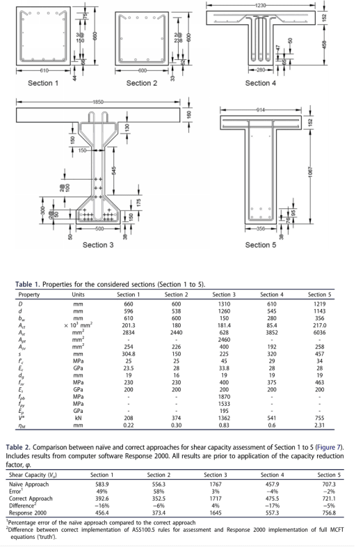
If they were matching phi.Vu (which is the right way IMO), V*=374 resulted in phi.Vu=389. They almost match already. Iteration should do little.
RE: Recommendation to scale factored action effects to determine shear capacity for load rating
Load rating of shear without the use of the proposed approach is useful as the rating can give an indication of relative shear carrying capacity of different bridges in the network for the same rating vehicle. The rating conforms to MCFT. Load rating by the modified approach using Vu(approach) and V*(AS 5100.7) does not conform to MCFT so is not suitable to use for the purpose stated in the first sentence.
Since MCFT uses strength that is a function of several load effects and many of the equations used have non-linear terms, care must be taken in coming up with a procedure for load rating and how to use the information obtained. See the comment from Holt et al about taking care in using load rating results.
"A typical MCFT-based shear-moment interaction diagram for a generic section is provided in Figure CB5.2-6 of the current LRFD Bridge Design Specifications, which shows non-linearity over the range of applied moments. This figure should remind load rating engineers that simple linear ratios in capacity, and hence rating factors, may give incorrect results."
page 91 of report
Holt, J., Garcia, U., Waters, S., Monnopolis, C., Zhu, A., Bayrak, O., Powell, L., Halbe, K.,Kumar, P., and Chavel, B. (2018). Concrete bridge shear load rating, Synthesis report.U.S. Department of Transport Federal Highway Administration, November
In previous standards where is shear capacity is not dependent on other action effects, the type of logic you described can be used as the capacity is more or less invariant. With MCFT, the ratio (phi.Vu - V*g) is not constant with changes in loading. This is a non-linear problem and ideally a rigorous assessment procedure (e.g. building load rating into structural analysis programs) should be used for heavy vehicle movement assessment.
Also, I do not think the use of the assumed proportional loading of load effects to give V*(approach)= Vu(approach) is useful.
The approach results in the following:
A new shear capacity Vu (approach) as been obtained for a system (bridge and load rating vehicle) x Vu(approach)/V*(AS 5100.7), since load and other safety factors should not be scaled. This capacity is not suitable for calculating LR for the nominated rating vehicle on the bridge since it uses a strength that is not consistent with the applied loading. Note that if Vu(approach)/V*(AS 5100.7) is less than unity, the dead and permanent load has been scaled down as well !!
My opinion is that the correct way to present the outcome caused by using the proposed approach is as below (to enable conformation to MCFT).
Clearly states that the load rating is for a bridge vehicle system with the dead and live load both multiplied by a factor Vu(approach)/V*(AS 5100.7) where V*(AS5100.7) is the factored shear of AS 5100.7.
The load rating factor LR is to be calculated as
phiVu(approach) - [V*(DL)(AS5100.7) x Vu(approach)/V*(AS 5100.7)]
---------------------------------------------------------
V*(LL)(AS5100.7) x Vu(approach)/V*(AS 5100.7)
Usefulness of the approach?
RE: Recommendation to scale factored action effects to determine shear capacity for load rating
The issue that makes me pause is that the MCFT capacity is only on paper. It can't necessarily be used. Is it really the capacity that the numerator in the rating factor calls for? Scaling up the vehicle load doesn't match the definition of the denominator, but gives you a real numerator.
I didn't follow your comment about scaling the dead load.
RE: Recommendation to scale factored action effects to determine shear capacity for load rating
At the origin. V* (and the corresponding M*) is zero and P=0.
At the point V*2, the shear is V*2.as5100.7. The corresponding capacity is Naive2(as5100.7) and the corresponding moment is M*2.as5100.7. I added "as5100.7" to show that these are factored load effects of the full bridge vehicle system, say Pas5100.7. The coefficient etaM is calculated as M*2.as5100.7/V*2.as5100.7.
After using the assumed loading (which is not an actual loading) and the iterative solution procedure, the ultimate shear capacity is now Correct(proposed). the word "proposed" to show that it is from the proposed approach. The converged solution also gives a corresponding shear equals to Correct(proposed), since V=Vu at the intersecting point. As can be seen from the diagram for this scenario, the strength correspond to a reduced shear equals to Correct(proposed). We then relate the shear back to the loading. Since V*2.as5100.7 is the shear for the full system load and Correct(proposed) is the shear of the new strength, what is the loading in relation to this shear?
At origin the load is V=0, M=etaM x 0 =0, And load P=0
At V*2.as5100.7, the shear is V*2.as5100.7 and the moment is V*2.as5100.7 x etaM=M*2.as5100.7 . The load is Pas5100.7
At the intersection point, the shear is Correct(proposed), and the moment = eta_M*shear = eta_M* Correct(proposed).
The load is P x Correct(proposed)/ Pas5100.7
So the capacity thus obtained is for a loading = full load system Pas5100.7 scaled by a factor Correct(proposed)/as5100.7.
For this scenario, it is < 1.0
RE: Recommendation to scale factored action effects to determine shear capacity for load rating
Thanks, I did have a look at the issues raised in the article some time ago. I'll have a re-read and read discussion above to see if I have anything to add.
Doug Jenkins
Interactive Design Services
http://newtonexcelbach.wordpress.com/
RE: Recommendation to scale factored action effects to determine shear capacity for load rating
Thank you Doug.
Please note that it was stated in the paper that "iteration is required for capacity assessment as discussed in various publications such as Collins and Mitchell (2014)". The capacity assessment in the paper by Collins and Mitchell was carried out to determine shear strength at failure of a test structure subjected to monotonically increasing load to failure. Since the shear strength at failure where Vn=Vu is not known beforehand an iterative solution search procedure had to be used. The loading assumed in the analysis characteristic was used in the calculation. Such iterative solution search procedures are commonly to predict MCFT-based shear strength of test structures tested to collapse. For example, an iterative solution search procedure (sort of) was used in the study by Rajakaruna, Vanisssorn and Wong for the prediction of failure shear strengths of bridge beams tested in the laboratory.
(link: https://doi.org/10.1080/13287982.2022.2060546).
On the other hand, shear strength determination to AS 5100.7 is different as the loading is for a bridge with a moving rating vehicle. At any instance of loading, the ultimate capacity can be calculated directed from the corresponding load effects. No iteration is required. Also, the loading is not progressively increased to cause collapse.
RE: Recommendation to scale factored action effects to determine shear capacity for load rating
The shear strength of a beam is the shear strength of a beam. It does not care what loads are applied to it.
The MCFT will overestimate the shear strength if the applied loads are less than the capacity, because you are determining the capacity based on a combination of loads that are not actually present when the beam is at the brink of shear failure. The loads definitely need to be scaled up proportionally, which will bring the capacity down, and meet somewhere in the middle. Think about a situation where the applied loads are effectively zero; you will end up with a much larger capacity than if the loading was greater, which makes no sense. The capacity should not depend on the loads that are applied.
On the other hand, the MCFT will underestimate the shear strength if the applied loads are greater than the capacity, which would happen for things like load capacity assessments of bridges where we are determining the load rating for a heavy truck. In this case, there is additional capacity to be squeezed out of the model by scaling down the loads to the point where the beam is at the brink of shear failure.
RE: Recommendation to scale factored action effects to determine shear capacity for load rating
But there are outstanding issues, the main one being related to:
I don't think I agree with that (but perhaps I don't correctly understand how it would be implemented). The main problem I see with it is in calculation of the additional load on the longitudinal steel.
The procedure (I think) complies with the code is:
- Find Vuc and Vus by iteration (with no phi factor applied)
- Find the area of longitudinal steel required for the additional longitudinal force.
- Find the unfactored moment capacity of the section (Mu) with the reduced longitudinal steel area.
- If phim.Mu < M* then adjust V (section total unfactored shear capacity), and the associated M, by iteration so that Mu = M
- Then phiv.Vu = phiv.V and phim.Mu = phim.M
Certainly the code is not clear about the procedure for the case where the shear capacity is controlled by the longitudinal steel, and the recent supplement to AS 3600 is not helpful, it basically says just follow the code.
Also I doubt that the following statement from AS 3600 Supplement is always true:
C8.2.8 Proportioning longitudinal reinforcement
...
Alternatively, for reinforced concrete members subjected solely to bending and shear stress resultants, it is conservative to extend the longitudinal reinforcement needed to resist flexure alone by a distance of dv.cot(Thetav) past the section where it is theoretically no longer required for bending, in the direction of increasing shear.
Note that the code Cl 8.2.8 also requires there are "no sudden changes in the calculated tension force", but this is not mentioned in the supplement.
Doug Jenkins
Interactive Design Services
http://newtonexcelbach.wordpress.com/
RE: Recommendation to scale factored action effects to determine shear capacity for load rating
My comments were also assuming that simple extension of the longitudinal reinforcement per C8.2.8 is adequate. I don't have the appetite to reduce effective bending reinforcement for routine work. But that does clarify the intent of the paper/method in question, so thanks.
RE: Recommendation to scale factored action effects to determine shear capacity for load rating
Yes, I agree.
I think this raises an important point regarding the Caprani and Melhem paper. In their "naïve" approach they use V* as the target shear capacity Vu, but V* must be >= phi.Vu, which is why this approach may indicate a section with inadequate capacity is OK. To do the check without iteration the input shear and moment should be V*/phi and M*/phi, just as in checking combined moment and axial load the calculation is done with axial load/phi, and the resulting actions are multiplied by phi for the design capacity.
In my opinion the requirements for additional longitudinal steel and/or extension of the longitudinal steel are confusing and are inconsistent between AS 3600 and AS 5100.
In AS 3600 the alternative of extending the reinforcement is given as an alternative in Cl 8.2.8 (Proportioning longitudinal reinforcement), but it states there should be no sudden changes in the calculated tension force, which presumably means it can't be used when there are applied point shear forces.
In AS 5100 the procedure for extending the reinforcement is given in a separate clause (8.2.9), but it makes no reference to sudden changes in the calculated tension force, which presumably means it can be used when there are applied point shear forces.
I would be interested in knowing how others handle this in practice.
Doug Jenkins
Interactive Design Services
http://newtonexcelbach.wordpress.com/
RE: Recommendation to scale factored action effects to determine shear capacity for load rating
The link to the open access article is:
https://www.mdpi.com/2412-3811/7/11/156
RE: Recommendation to scale factored action effects to determine shear capacity for load rating
AS 5100.7 defines the Load Rating Factor as:
3.10: A ratio of the available bridge capacity for traffic load effects to the traffic load effects of a nominated rating vehicle (see Clause 14).
To find that you need to find the combination of effects (bending moment, shear, torsion and axial load) that cause the most severe combined effect, and then find the factor on the vehicle loads that would cause the combined effects to reach the section's Ultimate Limit State.
Where the capacity depends on the combined loads, such as combined bending and axial load, or combined bending and shear, then the loads need to be factored to get an accurate value for the capacity.
To do this it seems to me that the simplest approach is to plot an interaction diagram of section capacity, then plot all the load points for different vehicle positions, and for different sections with the same capacity. It is then straightforward to find the minimum load rating. This is standard practice for combined bending and axial load, and I don't see why you wouldn't adopt the same approach for combined bending and shear.
One other point: For checking the shear effect on longitudinal reinforcement in AS 3600 all the effects are combined to find the total force on the tension steel, and the applicable capacity reduction factor is the factor for bending capacity. In AS 5100.5 the steel capacity for longitudinal force due to shear is factored down by the shear reduction factor, which doesn't make sense to me, since the steel will be equally ductile no matter where the force is coming from.
Doug Jenkins
Interactive Design Services
http://newtonexcelbach.wordpress.com/