×
INTELLIGENT WORK FORUMS
FOR ENGINEERING PROFESSIONALS

Log In

Come Join Us!

Are you an
Engineering professional?
Join Eng-Tips Forums!
  • Talk With Other Members
  • Be Notified Of Responses
    To Your Posts
  • Keyword Search
  • One-Click Access To Your
    Favorite Forums
  • Automated Signatures
    On Your Posts
  • Best Of All, It's Free!

*Eng-Tips's functionality depends on members receiving e-mail. By joining you are opting in to receive e-mail.

Posting Guidelines

Promoting, selling, recruiting, coursework and thesis posting is forbidden.

Students Click Here

Clamp load hole stress

Clamp load hole stress

Clamp load hole stress

(OP)
I've modeled a rectangular tube being clamped via a pretensioned bolt:
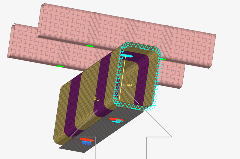
The tube is 10 mm thick (steel) and is fixed at one end. The pretension force is 50 kN.
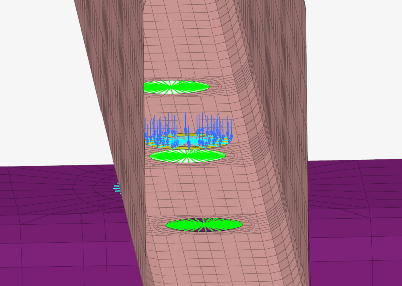
I also modeled a 50 kN nodally-distributed force on the washers of another connection, to compare the results:
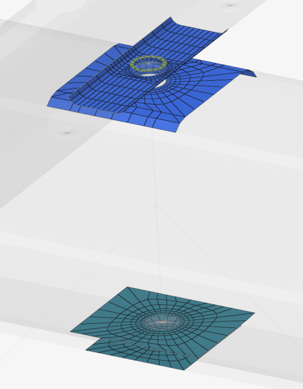
The contacts between the components are set to "friction" with a coefficient of 0.7:
The simulation is a non-linear static analysis.
The stress results are very large. Especially around the hole edge:
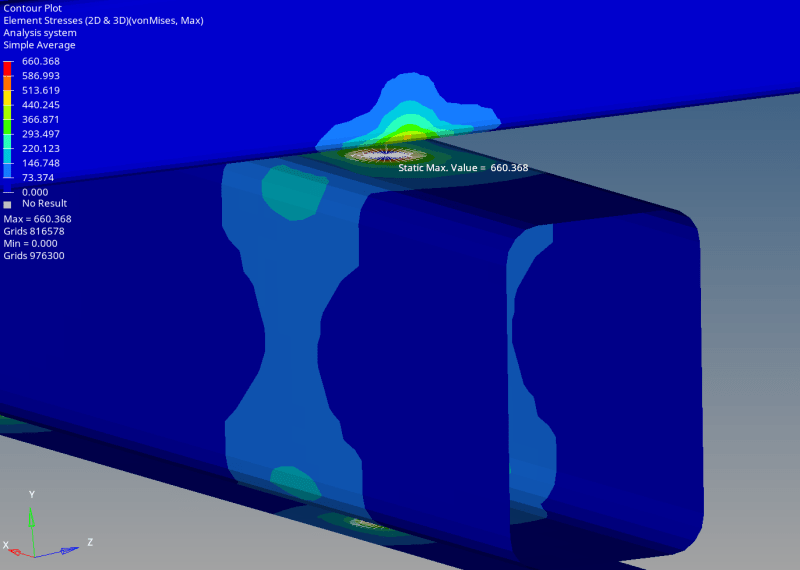
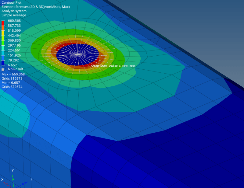
I realize that 660 MPa is an overestimation as the stress is beyond the yield stress. But these results suggest yielding around the hole.
Additionally, the deformation results show a deformation of 0.2 mm at the hole edge:
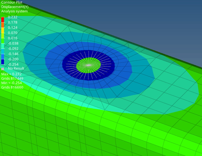
However, just from experience/intuition, it is obvious that torquing a bolt to spec (50 kN clamp load) will not cause a 10 mm thick tube to yield.
I had a test done. After torquing the bolt 50 kN, the bolt deflected 0.1 mm (not 0.2 mm as predicted by the simulation). Upon release, the tube sprang back with no evidence of plastic deformation.
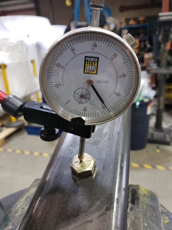
Why are the simulation results much larger than reality?
How should I accurately simulate this configuration?
Replies continue below

Recommended for you

RE: Clamp load hole stress

When you say that the analysis is nonlinear, do you mean that it also includes nonlinear material behavior - plasticity ?

RE: Clamp load hole stress

(OP)
The material is linear, which is why I'm ignoring the actual stress values beyond yield, and just noting the fact that the material has reached yielding.
The nonlinear analysis is to allow for changing contact status. If I set a frozen/bonded contact between the components, I get additional stress concentrations (not extreme) at the borders of the contacts and lower overall stresses which I think are a result of artificially forcing the load to distribute evenly over the contact area.

RE: Clamp load hole stress

I would definitely run this analysis with plasticity included. It not only provides more realistic stress values but also allows for stress redistribution. The yielding regions may also change significantly when compared with a study involving linear elastoc material.

RE: Clamp load hole stress

(OP)
Wouldn't including pasticity just give me a more detailed simulation of the post-yield behavior? I'm saying that the current results that are showing yield seem way too high, especially since the physical test shows a much smaller deformation and no signs of plastic deformation.

RE: Clamp load hole stress

You are using rigid elements which are infinitely stiff and give incorrect (rubbish) results at the connections to those elements.

RE: Clamp load hole stress

(OP)
@SWComposites, can you elaborate?
The 1D elements on the washers are RBE2 elements but the 1d elements in the other components are RBE3 elements.

RE: Clamp load hole stress

Rigid elements are infinitely stiff. Therefore they result in stress singularities. All stresses connected to rigid elements are incorrect, usually excessively high. Thus they are typically ignored.

RE: Clamp load hole stress

"Wouldn't including pasticity just give me a more detailed simulation of the post-yield behavior? "
You have no information at all about post-yield behavior if you run analyses with linear elastic material properties.

"I'm saying that the current results that are showing yield seem way too high, especially since the physical test shows a much smaller deformation and no signs of plastic deformation."
The test shows 50% of the deformation, according to your post, but you did not specify the accuracy of your experiment. A deflection gauge will not be able to provide you with good accuracy, and the uniaxial deflection measurement cannot be tied to an analytical formula that will give an accurate cross-check of the FEM calculation. In short, your experimental setup is not suitable.

You need to use digital image correlation or a similar technique to record strains (to be compared to calculated strains) experimentally.

PS. You have used very few elements and also displayed stresses and deflections averaged from multiple neighboring elements. The solution to this problem is very sensitive to the assumptions made at every step of the way, unlike e.g., simple beam bending, so I would suggest mesh refinement, ditching the obviously severe averaging technique in post-processing, using a plastic material model (or re-defining plate thicknesses until only very few areas are stressed beyond yield), and ensuring that you are not connecting rigid links to shells - those screw up calculations more than anything else.

Red Flag This Post

Please let us know here why this post is inappropriate. Reasons such as off-topic, duplicates, flames, illegal, vulgar, or students posting their homework.

Red Flag Submitted

Thank you for helping keep Eng-Tips Forums free from inappropriate posts.
The Eng-Tips staff will check this out and take appropriate action.

Reply To This Thread

Posting in the Eng-Tips forums is a member-only feature.

Click Here to join Eng-Tips and talk with other members! Already a Member? Login


News


Close Box

Join Eng-Tips® Today!

Join your peers on the Internet's largest technical engineering professional community.
It's easy to join and it's free.

Here's Why Members Love Eng-Tips Forums:

Register now while it's still free!

Already a member? Close this window and log in.

Join Us             Close