Alignment pegs GD&T
Alignment pegs GD&T
(OP)
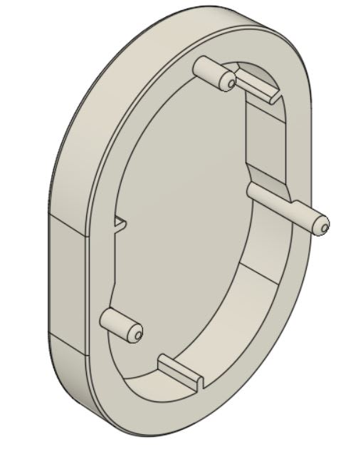
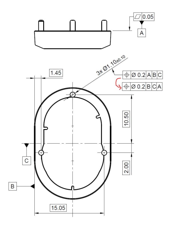
I am trying to apply GDandT to alignment pegs/pins on an injection molded part. I made two different ways to define the pegs, are both correct? Is there something wrong with the right-side drawing?
Thank you for taking the time to help out.
RE: Alignment pegs GD&T
This is how the part looks for reference.
RE: Alignment pegs GD&T
All your Datum Feature symbols should be attached to physical features specified as Datum Features. They should never be applied to theoretical planes, lines, or points. Theoretical datums (planes/lines/points) are derived from the physical Datum Features (or more accurately, their inverse Datum Feature Simulators). Notice the slot Datum Feature symbols in your attachment are applied to the width NOT the center line/plane.
RE: Alignment pegs GD&T
So on the female part, (which is similar to the above part but instead of pins it has holes where the pins can go) do I dimension it similar to what i did above? And also do I need to provide an mmc on the holes?
Also the part is injection molded..
RE: Alignment pegs GD&T
Is it a plastic or a metal part?
RE: Alignment pegs GD&T
Edit: the above was addressing the first file you posted.
RE: Alignment pegs GD&T
And on the right side drawing, I think the datum E is wrong from what I learned above.
RE: Alignment pegs GD&T
Which is the governing standards?
RE: Alignment pegs GD&T
Primary datum reference A locks 3 degrees of freedom: 2 rorations (initial stabilization), and 1 translation. Seconday datum reference B locks the other 3 degrees of freedom: translations in 2 directions, and the remaining rotation.
MMC, MMB as shown appropriate if the main concern is about the parts fitting together and less about alignement.
RE: Alignment pegs GD&T
Also the drawing follows iso standard if I am not wrong?
RE: Alignment pegs GD&T
It makes the most sense to control the rest of the part features with profile referencing A primary, B secondary. It will control the form and size, as well as location and orientation of the surfaces with respect to the "datum reference frame"/"datum system". The all-around profile on the internal geometry was just an example. You can choose the tolerance values. If you have any features critical for function, control them with a tighter tolerance. If nothing is particularly important, you could specify a loose general profile tolerance on all surfaces, and direct to the CAD model for query for all the basic dimensions that are not specified.
RE: Alignment pegs GD&T
BTW, please ignore the basic dim. 17.4 in my suggestion sketch. It is redundant.
RE: Alignment pegs GD&T
"Repetitive features or dimensions may be specified by the use of an X in conjunction with a numeral to indicate the “number of places” required"
It is para. 1.9.5 in the 2009 edition and 4.6.5 in the new (2018) edition.
In ISO lowercase "x" is used.
RE: Alignment pegs GD&T
Yes, you are correct.
My example is not a complete drawing. All other surfaces of the part, including the external geometry, can be controlled with reference to datum features A and B.