Modelling of transformer and MV cable for harmonic studies
(OP)
For my research project, modelling is needed for dyn5 630 kVA transformer and 20 kV cable NA2XS(F)2Y to do harmonic analysis. For that i need leakage reactance, and resistance of copper losses for transformer. And following parameters for 20 kV cable are also needed.
Positive, negative and zero sequence of resistance, reactance and susceptance.
Can anyone help in it?
Positive, negative and zero sequence of resistance, reactance and susceptance.
Can anyone help in it?
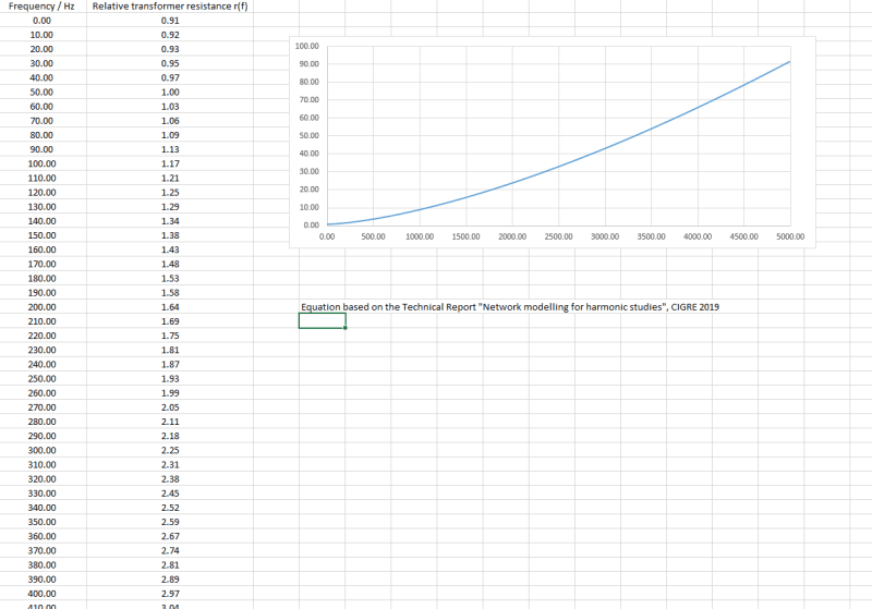
RE: Modelling of transformer and MV cable for harmonic studies
In these conditions Z=27 to 32 ohm [from 20 kV side ] then X=26.5 to 31 and R=5.2 to 6.2 ohm.
The cable NA2XS(F)2Y 20 kV according to IEC 60502-2, IEC 60228 and manufacturer catalogue r[ac.90oC]=1.13 ohm/km ; x[50 Hz]=0.1455 ohm/km trefoil or 0.2036 ohm/km flat
RE: Modelling of transformer and MV cable for harmonic studies
I suspect Zanoter's response is for a single frequency point (typically line frequency). Use the mathematical relationship for calculating inductance (and/or capacitance) for the line frequency condition to get the non-frequency components based on Zanoter's estimates. Then plug in the frequencies of interest to obtain your "predicted" curve.
Converting energy to motion for more than half a century
RE: Modelling of transformer and MV cable for harmonic studies
If we should transfer the theory in transformer case, we don't know the conductor details in such a way to calculate nor skin neither proximity effect. There are a lot of publications connected with but most of them are for cable usually.
RE: Modelling of transformer and MV cable for harmonic studies
https://www.electricalengineeringtoolbox.com/2014/...