Navigation
Install the app
How to install the app on iOS
Follow along with the video below to see how to install our site as a web app on your home screen.
Note: This feature may not be available in some browsers.
More options
Style variation
-
Congratulations cowski on being selected by the Eng-Tips community for having the most helpful posts in the forums last week. Way to Go!
You are using an out of date browser. It may not display this or other websites correctly.
You should upgrade or use an alternative browser.
You should upgrade or use an alternative browser.
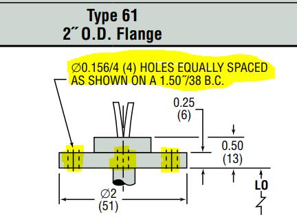
Unfamiliar dimensional call-out. Help needed. 1
- Thread starter CanosSSCS
- Start date
- Status
- Not open for further replies.
-
1
- #2
Not the correct way to dim.
But, 1.50 eq sp means the 4 holes are eq sp on that dia, 90 deg apart. But, does not show the orientation to the part.
ctopher, CSWP
SolidWorks '19
ctophers home
SolidWorks Legion
But, 1.50 eq sp means the 4 holes are eq sp on that dia, 90 deg apart. But, does not show the orientation to the part.
ctopher, CSWP
SolidWorks '19
ctophers home
SolidWorks Legion
Are there any more views on that drawing?
Type 61 sounds enough like Code 61 to make me wonder.
Type 61 looks to be a "standard" in industries that use pipe for light duty structural service.
Not much like your image. Countersunk bolt holes for a start.
Type 61 sounds enough like Code 61 to make me wonder.
Type 61 looks to be a "standard" in industries that use pipe for light duty structural service.
Not much like your image. Countersunk bolt holes for a start.
mfgenggear
Aerospace
Old school prior to GD&T. For 1/4 soc hd screws. Old timers held the True position required for assembly. 3Ddave is correct. Being it was on a diameter.
- Status
- Not open for further replies.
Similar threads
- Locked
- Question
- Replies
- 21
- Views
- 2K
- Locked
- Question
- Replies
- 11
- Views
- 5K
- Replies
- 1
- Views
- 540
- Locked
- Question
- Replies
- 9
- Views
- 1K
- Question
- Replies
- 7
- Views
- 913

