×
INTELLIGENT WORK FORUMS
FOR ENGINEERING PROFESSIONALS

Log In

Come Join Us!

Are you an
Engineering professional?
Join Eng-Tips Forums!
  • Talk With Other Members
  • Be Notified Of Responses
    To Your Posts
  • Keyword Search
  • One-Click Access To Your
    Favorite Forums
  • Automated Signatures
    On Your Posts
  • Best Of All, It's Free!

*Eng-Tips's functionality depends on members receiving e-mail. By joining you are opting in to receive e-mail.

Posting Guidelines

Promoting, selling, recruiting, coursework and thesis posting is forbidden.

Students Click Here

Plotting the System Curve for Dissimilar Pumps Operated in Parallel.

Plotting the System Curve for Dissimilar Pumps Operated in Parallel.

Plotting the System Curve for Dissimilar Pumps Operated in Parallel.

(OP)
Hi All.

I want to continue the discussion from the thread ( link copied below).

https://www.eng-tips.com/viewthread.cfm?qid=491906

We are in the process of operating two dissimilar pumps parallelly. Apart from being differently sized pumps, the pump suction lengths are not same. the discharge piping up to the common junction is also different in length. My question is the system curve of which pump should I use for getting the duty point on the composite curve. Should I use the smaller pump with longer suction and discharge piping to common point or the larger pump with shorter suction and discharge piping to the common point. I will draw the piping isometrics tomorrow.

Thanks and Regards,
Pavan Kumar


Replies continue below

Recommended for you

RE: Plotting the System Curve for Dissimilar Pumps Operated in Parallel.

Unfortunately you need to have separate system curves that will have a single unified pressure value where the two pump discharges come together. Create 3 system curves - one for the suction and discharge of pump 1 up to the tie-in point, one for the same for pump 2, and one for the combined discharge line. With known pump suction pressures and final discharge pressure, iterate flows such that

Flow(p1) + Flow (p2) = Flow (p3)
AND
P1 - friction losses(Fp1) + dP(P1) = Pj
(P1 = starting suction line pressure, friction losses (Fp1) = friction losses due to Flow(p1), dP(P1) = pump head, Pj = tie-in point pressure)
AND
P2 - friction losses + dP(P2) = Pj
same as P1, except for P2
AND
Pj - friction losses(Fp1+FP2) = Pf
(Pf = final discharge pressure)

This will be quite a complicated spreadsheet. Pj is an unknown and flows are unknown, but you have sufficient degrees of freedom to solve this. Be prepared for Excel to sometimes crash during your manual iterations if you drive a negative value inside a square root term.


OR....build a model of this in a flow simulator and it will do most of this work for you!

RE: Plotting the System Curve for Dissimilar Pumps Operated in Parallel.

(OP)
Hi TiCl4,

I will work through your suggestions. Thank you very much.

Thanks and Regards,
Pavan Kumar

RE: Plotting the System Curve for Dissimilar Pumps Operated in Parallel.

Agree with both above.

You issues usually start when pumping two units that if the pump curves vary, then you need to work out at what flow one pump will be doing 100% of the flow.

In reality you need to find the min flow though the "weaker" of the two pumps, understand what the head is at the common point and then work backwards to find the minimum combined flow. At that point any flow lower will be damaging the weaker of the two pumps or dead heading it.

The only common thing in the two systems is the pressure at the point where the two streams combine and possibly the same inlet conditions at the tank?

Work backwards from there.

It's the two pump curves you need first, then add in the losses in the pipework.

Remember - More details = better answers
Also: If you get a response it's polite to respond to it.

RE: Plotting the System Curve for Dissimilar Pumps Operated in Parallel.

FYI, The approach MortenA posted is much simpler, but also relies upon the losses in the suction line and discharge line up to the tie-in point for each pump are either similar to each other at all operating points or are negligible compared to losses after the tie-in point (as seen by the existence of only one system curve).

You could check max expected flow through each pump, and if losses before the tie-in point are less than, say, 5% of total losses, you could move forward with the approach he suggested with assurance of reasonable accuracy.

I especially agree with LI’s point of checking minimum required flow on the lower head pump and makings sure you operate above that point.

RE: Plotting the System Curve for Dissimilar Pumps Operated in Parallel.

Hi,
I suggest you and other to download : PUMP SYSTEM IMPROVEMENT TOOL using your favorite search engine and use the examples library to set up up and simulate your own system .
First of all you need to get the pumps curves.
Good luck
Pierre

RE: Plotting the System Curve for Dissimilar Pumps Operated in Parallel.

(OP)
Hi TiCl4,MortenA, LittleInch and pierreick,

I have the pump curves for both the pumps. Thank you all for the very good suggestions and ideas give n to me. The procedure I am going to follow is follows. Please let me know if I am missing anything.

1. For each flow rate( flow in the common line for both pumps) on the system curve, I will iterate the flows in each pump branch starting the pump suction and discharge till the pressure at the tie-in point is same. Both pumps draw the liquid( tepid water) from the tank through separate nozzles.
2. I will then calculate the pressure drop in the common line using the pressure calculated in step 1.
3. I will vary the flow rates over a range and repeat steps 1 and 2 to calculate the pressure drops in pump suction and discharge lines. Since the pressure drops in the pump suction and discharge until the tie-point will be same for both branches, I can easily calculate the differential head for each flow rate.
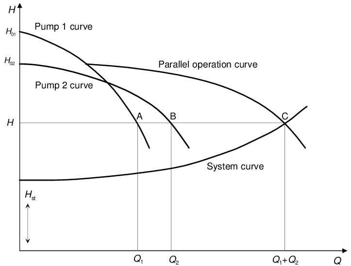
4. I will plot the pump curves for both the pumps and plot the composite pump curve by adding the flow rates for the various heads. I am aware that if the operating point is above the shut-off head of the smaller pump then the smaller pump will be forced to dead head. I will check where the system and pump curves will intersect and check this. I will also check to make sure that the operating point is above the minimum required flow of the smaller pump.
5. I will read the paper given by MortenA today.
6. I will post the results after I finish my calculations today on this thread. I got to have the isometrics drawn first.

Thanks and Regards,
Pavan Kumar


Red Flag This Post

Please let us know here why this post is inappropriate. Reasons such as off-topic, duplicates, flames, illegal, vulgar, or students posting their homework.

Red Flag Submitted

Thank you for helping keep Eng-Tips Forums free from inappropriate posts.
The Eng-Tips staff will check this out and take appropriate action.

Reply To This Thread

Posting in the Eng-Tips forums is a member-only feature.

Click Here to join Eng-Tips and talk with other members! Already a Member? Login


News


Close Box

Join Eng-Tips® Today!

Join your peers on the Internet's largest technical engineering professional community.
It's easy to join and it's free.

Here's Why Members Love Eng-Tips Forums:

Register now while it's still free!

Already a member? Close this window and log in.

Join Us             Close