de Havilland Comet Design changes
(OP)
I am trying to learn the specific design related issues with the de Havilland Comet. I have read the investigation report which spoke of:
1. Underestimation of stresses at the corners
2. Overloading the fatigue specimen before the fatigue test itself
3. Testing only the fwd fuse and effect of end restraints
etc
What I am interested however is the specific changes that were made to the design to make it airworthy again. Possible amends I could think of (based on my limited knowledge) were:
1. Reduction of general stress levels by making the skins thicker
2. Better materials in terms of crack resistance/growth (fracture toughness?)
3. Changing some of the cutout profiles to reduce the Kts.
4. Adding stiffners around windows to allowing stress away from the cutouts
But I was hoping for some definitive answers rather than guessing. An ideal answer would be one which compares the old and new design almost side by side. While a lot seems to written about what led to the accident, I couldn't find much by the way of specific design changes that were incorporated to make it airworthy again. Any pointers in that direction would be great! I will also welcome less than ideal answers ☺️.
RE: de Havilland Comet Design changes
B.E.
You are judged not by what you know, but by what you can do.
RE: de Havilland Comet Design changes
I don't think "Underestimation of stresses at the corners" is correct (though it may be the commonly held opinion). I think, remembering reports I've read a long time ago, they ran their fatigue test on the static test airframe ... and this was a (the) major problem with their approach (in the 50s).
I'd've thought there was something out there discussing the differences between the Comet 1 and the Comet 4. But the details you want are probably buried deep in the engineering data.
another day in paradise, or is paradise one day closer ?
RE: de Havilland Comet Design changes
https://www.raes-hamburg.de/media/files/text_2019_...
RE: de Havilland Comet Design changes
If you want to see the changes, you can look at the comet 4 or nimrod structural ipc and srm and compare to the comet 1. There are also RAE papers showing the stress investigations around cutouts.
As for other significant sources, you could always contact The Hub at farnborough and get a copy of the full original accident investigation as I did many years ago. Beware, it is quite large (over 1000 pages) and expensive to obtain a copy.
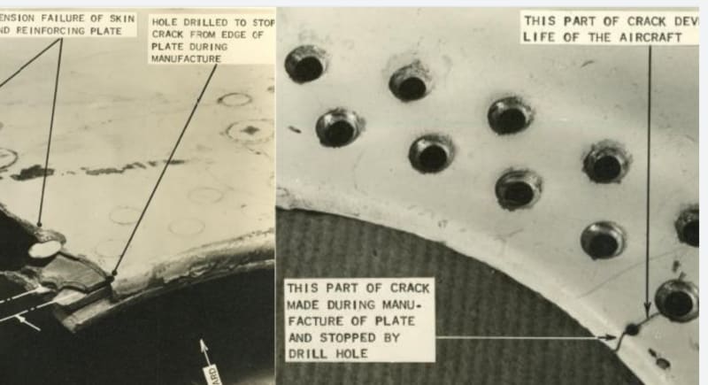
By the way, little advertised fact is that the structure recovered from the accident aircraft had stopped drilled cracks in numerous areas around the adf cutouts. The stopped drill cracks where a result of the punch drilling opertion dehavilland employed on the early produced aircraft. It is discussed in the public hearings but was written off as standard practice. Note the subsequent full scale fatigue test by RAE did not replicate the failures at the ADF cutouts in the crown of the fuselage but instead showed failures at the cabin windows and the test article did not have any stopped drilled cracks. The punch drilling operation induced damage in the holed thru "ripping" of the material.
If you search online, I presented a paper at AAS 2017 which shows the stop drilled cracks and also presented some of it at ASIP 2021, you might be able to find the papers online. Also, Dr Paul Withey has presented several papers on this topic and confirmed the presence of damage in the original panel at the ADF cutouts. Not to say high stresses were not significant, which they obviously were, but if you include at least 4 or more stopped drilled cracks in the same area, the stresses would be even higher.
Anyway, the comet is a great case study and still has some valuable information for learning.
good luck in your efforts.
RE: de Havilland Comet Design changes
another day in paradise, or is paradise one day closer ?
RE: de Havilland Comet Design changes
another day in paradise, or is paradise one day closer ?
RE: de Havilland Comet Design changes
another day in paradise, or is paradise one day closer ?
RE: de Havilland Comet Design changes
another day in paradise, or is paradise one day closer ?
RE: de Havilland Comet Design changes
another day in paradise, or is paradise one day closer ?
RE: de Havilland Comet Design changes
Especially starting at the heading "PART XI INVESTIGATION OF THE ACCIDENT TO G-ALYP AND G-ALYY"
Keep em' Flying
//Fight Corrosion!
RE: de Havilland Comet Design changes
another day in paradise, or is paradise one day closer ?
RE: de Havilland Comet Design changes
And there you see why the Paris equation is in the prescribed methods today.
Not a lot of presentations take the historical evidence and carry through with it in a fully developed analysis. That presentation does it, bridges the gap between general discussions and a tech report. Could be useful...
RE: de Havilland Comet Design changes
https://youtu.be/K5HqEwbp4GA
While I find it immensely useful, it falls short of the design measures used to prevent the kind of crack propagation observed.
RE: de Havilland Comet Design changes
I thought you can almost reliably never stop a crack from initiating. All you can do is to ensure that when one starts, you have designs in place to slow them down until the inspections pick them.
So, on the Comet, I think it's the fast and unarrested propagation that was the problem rather than the apperance of the crack
itself cause, I think one way or the other, a crack would have appeared with increased usage either due to manufacturing defects or otherwise.
In summary, given the structures sensitivity to crack initiation and given that cracks would have appeared with usage, I doubt if preventing cracks from appearing during manufacturing would have gone enough in the way to make it airworthy again.
Another pointer in that direction is a 707 marketing video released during that time which demonstrated slow crack growth when fuselage was penetrated by steel harpoons and I don't know if the Comet could have demonstrated that (slow propagation) given how sensitive it's to crack initiation itself.
I am willing to be wrong on the above prognosis but I think there is substantially more to Comet redesign than stop making cracks during manufacturing.
RE: de Havilland Comet Design changes
https://en.wikipedia.org/wiki/Redux_(adhesive)
RE: de Havilland Comet Design changes
"And there you see why the Paris equation is in the prescribed methods today." ... Paris is good as a first cut but not a good final match to crack growth, if you're in the threshold region.
Personally, I look at the correlation and think ... I wonder if they tuned their analysis to suit the result they wanted ?
But then I'm a cynic ...
another day in paradise, or is paradise one day closer ?
RE: de Havilland Comet Design changes
ok, and de Havilland have good experience with bonding ... but it is a very tricky process to get right.
another day in paradise, or is paradise one day closer ?
RE: de Havilland Comet Design changes
https://reports.aerade.cranfield.ac.uk/discover
I discovered an intriguing document up front...
Behaviour of Skin Fatigue Cracks at the Corners of Windows in a Comet I Fuselage
By R. J. ATKINSON, W. J. WINKWORTH and G. M. NORRIS
LONDON: HER MAJESTY'S STATIONERY OFFICE 1962 FOURTEEN SHILLINGS
Also stumbled-on …
https://www.sciencedirect.com/topics/engineering/d...
FATIGUE FAILURE OF THE DE HAVILLAND COMET I
P.A. WITHEY, in Failure Analysis Case Studies II, 2001
Abstract
The de Havilland Comet I entered service in 1952, and became the first commercial airliner to be powered by jet engines. It was introduced as the flagship aircraft on the routes of the British Overseas Airways Corporation, and was hailed as a triumph of British engineering. However there were a number of accidents involving this aircraft, culminating, in 1954, in the loss of two aircraft in similar circumstances. These were Comet G-ALYP near Elba, and Comet G-ALYY near Naples. A Court of Inquiry was convened, and the task of discovering the cause of these accidents was given to the Royal Aircraft Establishment at Farnborough. The investigation explored a number of avenues, and finally gave structural failure of the pressure cabin brought about by fatigue as the cause of the accidents. The use of fracture mechanics methods not used in 1954 has enabled the analysis of these fatigue cracks to be made, and the initial defect size has been estimated to be approximately 100 μm in the case of G-ALYP. This is not incompatible with the manufacturing techniques of the time, and information regarding cracks in the cabin identified during manufacture. © 1997 Elsevier Science Ltd.
and many more 'related' books for sale...
An intriguing thought from tiny brain. The Comet was De Haviland's first 'cut' at design/test/build/make of a large pressurized aircraft. Boeing already had hundreds of pressurized piston aircraft flying [B-29s and it's many derivatives for instance] and was developing the B-47... so, perhaps, many of the lessons of pressurization had been already experienced by Boeing when it eased into the 367-80 ['Dash 80'] prototype... then designed/tested/built the early 707s and the KC-135A. Maybe?
SWAG, my part... the placement of turbojet engines below mid fuselage, with their high sonic vibrations [and potential for catastrophic failure with fire possibilities]... may have been a 'wild-card' to pressurization and engine safety problems. Boeing eliminated these as issues on it's aircraft by placing the engines [isolated] on pylons hanging from the wing.
Regards, Wil Taylor
o Trust - But Verify!
o We believe to be true what we prefer to be true. [Unknown]
o For those who believe, no proof is required; for those who cannot believe, no proof is possible. [variation,Stuart Chase]
o Unfortunately, in science what You 'believe' is irrelevant. ["Orion", Homebuiltairplanes.com forum]
RE: de Havilland Comet Design changes
another day in paradise, or is paradise one day closer ?
RE: de Havilland Comet Design changes
1- A constructional method for minimising the hazard of catastrophic failure in a pressure-cabin
(https://reports.aerade.cranfield.ac.uk/handle/1826...)
2-Pressure-cabin design a discussion of some of the structural problems involved, with suggestions for their solution
(https://reports.aerade.cranfield.ac.uk/handle/1826...)
Both papers were published right after the enquiry.
@WK Taylor: thankyou for that goldmine!!
RE: de Havilland Comet Design changes
Yes, 10in frame spacing would reduce the skin stress, but I'm pretty sure no one does that today (when we are more confident in our approach, as opposed to immediately after the accident), and I doubt the Comet was redesigned that way. Typical frame spacing in my experience is about 30". Less than that then the frames are broken at the window belt which introduces another design problem. Also they are using a high hoop stress ... 10' diameter, 0.028" skin thk, 9psi pressure >> hoop stress 19.5ksi ... this is about 50% higher than common practice today. Possibly they added sub frames and sills around the large cut-outs ... even though these were probably not the initiation site.
At this time, immediately after the accident, they didn't have time to appreciate the impact of using the static test article for the fatigue test.
Also, they had yet to drill down into the manufacturing processes used ... that punch drilling is sensible only if you're dimpling the skin (to save countersinking in the thin skin. Even then a two stage process (drilling then dimpling) would be used today. I don't think anyone punch drills rivet holes.
But still great references to add to the library ... it'd be interesting to compare their equivalent skin thickness approach for frames as compared with a FEA.
another day in paradise, or is paradise one day closer ?
RE: de Havilland Comet Design changes
Vans aircraft uses turret punch to make much of their aircraft sheet metal parts (starting to get into laser cut too, but that's another story). They pilot punch the rivet holes. Vans is quite adamant about match drilling, deburring, and edge prep... but I know a lot of builders who simply cleco the punched holes and start shooting rivets.
Looking at the anatomy of a hole punch process or even shear process at cross section on the sheetmetal it's obviously a 2 stage process where actual shearing occurs up to the point where compressive force exceeds that of the remaining materials shear strength then rips it out. That ripped out part is gross. I'd never leave that on an aircraft part... but I'm guessing they didn't know yet that back then???
RE: de Havilland Comet Design changes
"Vans aircraft" ... look to be kit planes (nothing wrong with that, I'm working on a kit project now), but definitely the shallow end of the pond. Very thin gauge sheet metal, very low cost manufacturing. If they take care to post-process and have done it for years ... who the heck are we to throw dispersions on their process.
another day in paradise, or is paradise one day closer ?
RE: de Havilland Comet Design changes
Fatigue qualities of airframe design details aren't as much of a concern as in transport aircraft... that was a hard line to read. But I suppose you're not wrong.
Though I am reminded of a 1967 cessna 182 I looked at a few months ago with 7400 hours total time. It was kinda rough... not to mention the reason I was looking at it was the lift strut AD... it was cracked.
RE: de Havilland Comet Design changes
and yes their fatigue expectations are different to OEMs ... their durability is lower 'cause their customers expect less. Cessna is not in this category, but yet a 50+ year airplane with <10000 hrs is very low utilisation.
another day in paradise, or is paradise one day closer ?
RE: de Havilland Comet Design changes
MANY moons-ago a couple of high-time retired 727-? fuselages were disassembled piece-by-piece for a technical/research evaluation for damage such as corrosion, fatigue, fastener-failures, spot-weld failures, etc study.
The relatively short cockpit structure and tail cone fuselage structures [compound curvature] sections were very consistent in their damage profiles, throughout.
HOWEVER... The oddest thing was noticed by the tear-down crew and verified statistically: the upper-LH crown constant-section, upper-RH crown constant-section and the floor/belly constant-sections each had uniquely different damage profiles. The researchers were baffled. The belly section was relatively uniform and was dominated by corrosion and loose fasteners. However... One crown section had relatively minor cracking, corrosion and loose fasteners [etc]. The opposite-side crown section was dominated by widespread cracking, loose/smoking fasteners, corrosion out-breaks, sloppy fits/gaps, etc. YES, the researchers were baffled.
SO, they contacted Boeing for technical assistance. The big question 'WHY' also stumped the Boeing folks... There was absolutely NO technical reason [stress/strain/aero/materials/processes/etc] as-to 'why' the crown sections should appears to have such uniquely different damage levels. Then someone got the bright idea to go back to the production floor for answers. Since 727 production had just been terminated many of the 'build' crew members were still available. The resulting insight changed the company.
Each of the [5] sections [cockpit/entry door, tapered-aft fuselage, LH upper crown-constant, RH upper crown-constant and the belly-constant] were mostly made the 'old-fashioned-way', IE: built-up by hand in huge assembly fixtures. OK... Sooooo? Well, It was discovered that the crews and leads building these sections were kept on these same sections thru the production years... IE: there were dedicated section crews/teams that rarely changed personnel thru the years... and RARELY/NEVER worked on any other section. Hmmmm... That was the key, unlocking this mystery.
The production crewmembers for the [2] upper crown constant-sections were interviewed... and what emerged was clearly stunning.
One crew had 'older/experienced lead /workers' dating back to WWII, which exhibited work and quality protocols learned during those early high production 'git-er-done' rates of WWII 1940s. This older crew had been working together on jobs like this since B-17, B-29 years and felt most comfortable working together thru the 1960s.
The opposite crew had younger leads/workers with more recent quality and production training protocols that had a greater emphasis on consistent/standardized workmanship and quality practices, etc that were more methodical, and slower, than the 'older-gray-hair team'. Assembly-close-shimming-to-fit, deburring, added touch-up primer, recurring jig/fixture maintenance and alignment inspections, etc were emphasized on this team.
The cockpit and tapered-aft fuselage teams were more of a blend of old/new workers and leads.
Yep... the upper crown sections made by the older work-team were the ones exhibiting much higher levels of damage. The upper crown sections made by the made by the younger/newer-trained work-teams had far less detectable damage and issues. In real terms the upper crown-section made by the older crew was the primary maintenance cause for removing these jets from service, in the first place. IF both crown-section's quality had been uniform... consistent with the younger crew's workmanship... these jets could have flown safely and productively and with lower structural maintenance... for many more years/hours to come.
This one study starkly revealed the immense value of consistent high quality assembly practices on useful life [fatigue and structural maintenance]. The long term resolution for Boeing was to hasten the drive for major/critical structural assemblies to be machine-assembled [wherever possible], to eliminate the issues/inconsistencies found in common 'hand-assembly workmanship'. This also led to larger/fewer assemblies built-up all at one time with machine/computing-following for every aspect of quality... tight dimensional controls for individual parts for precision fit/clamp-up, drilling, fastening, etc... and for higher quality corrosion protective finishes on the parts before assembly, so that added/touch-up finishes... including fay sealant, etc... were minimized/eliminated. And projected useful service lives have climbed above 100,000-hours and 25-years.
I wish I could find that report... had a paper 'summary' copy for years.
I personally have experienced MIL-Jets where LH/RH parts or assemblies are dimensionally inconsistent and do cause a unique host of issues during replacements... and even 'aerodynamic oddities' that were known, but understood... but were livable-with… so they were simply ignored.
Regards, Wil Taylor
o Trust - But Verify!
o We believe to be true what we prefer to be true. [Unknown]
o For those who believe, no proof is required; for those who cannot believe, no proof is possible. [variation,Stuart Chase]
o Unfortunately, in science what You 'believe' is irrelevant. ["Orion", Homebuiltairplanes.com forum]
RE: de Havilland Comet Design changes
Having a steady and dependable workforce can avoid making the "stupid" mistakes but can also allow poor practices to continue for long periods of time resulting in dependably inferior products. Sometimes getting a new guy on the job that everyone has to explain "why" to can help understand when the "why" is flawed.
It would also be recommended that stress and design engineers be on the fabrication and assembly teams to see if what they thought was going to happen actually did happen. Too often they don't want to get near metal chips and, similarly, too often the factory guys "know the job and don't need anyone looking over their shoulders."
RE: de Havilland Comet Design changes
He was match drilling some ribs to a trim tab spar. One of them was misaligned by about 1/32". I said absolutely not, throw that rib out and get a new one. He said where on the print does it call that out...
The moment he said it I realized he had me.
Took a new guy to find something out of control that's been in in production for 3 years.
RE: de Havilland Comet Design changes
1/32" is only 0.03 ... typically within drawing dimension tolerances ?? no?
Unless this was misplaced with the match drilled partner ? In which case why not go up a size ? eD issues ?
are you Inspection or Liaison ? Was the part not to B/P ? Would it be flagged by Inspection ??
If so, then typical non conformance paperwork (but no "gotcha")
Possibly match drilling is a process with understandably tight tolerances ? (or the assumption of tight tolerances ?)
another day in paradise, or is paradise one day closer ?
RE: de Havilland Comet Design changes
B.E.
You are judged not by what you know, but by what you can do.
RE: de Havilland Comet Design changes
In this case a spar cap was corrosion damage and needed the segment replaced [cutout/inert]. A straight-forward repair [after I designed the splice and had it approved].
After drilling/punching-out the old 3/16 and 1/4-D rivets, eddy current NDI detected [2] perfect/parallel straight 'defect line-indications'... tightly spaced thru-the-hole... on a couple of widely spaced holes. Close inspection [10X] revealed the 'moon-shaped slivers' of smaller 1/8-Dia rivets that had been partially drilled-thru for the final rivets. Huhhh??? Getting help from Boeing, someone identified the fact that the sub-assembly drawing allowed used of 1/8-Dia tack-rivets at various locations for holding parts together... which should have been fully drilled-thru/enlarged during final Assy for the fastener installs... but never were. Unbelievable.
Regards, Wil Taylor
o Trust - But Verify!
o We believe to be true what we prefer to be true. [Unknown]
o For those who believe, no proof is required; for those who cannot believe, no proof is possible. [variation,Stuart Chase]
o Unfortunately, in science what You 'believe' is irrelevant. ["Orion", Homebuiltairplanes.com forum]
RE: de Havilland Comet Design changes
Rib was misplaced to the spar. would have had a crease in the skin it was so far off.
Nope. Just an engineer that was watching over in intern learning the shop floor by doing a few simple projects.
RE: de Havilland Comet Design changes
you were looking over the shoulder of an intern (who was doing liaison) ? it's way too common a trend ... having interns doing liaison. in my day only the oldest, narliest, crankiest guys did liaison.
or you were the intern and had ventured down to the floor (pit?) to see what was going on ?
another day in paradise, or is paradise one day closer ?
RE: de Havilland Comet Design changes
Huh. Back when I was doing liaison, I didn't see you venture downstairs too often to join me, RB.
RE: de Havilland Comet Design changes
another day in paradise, or is paradise one day closer ?
RE: de Havilland Comet Design changes
Mounting the engines submerged in the wings reduces drag (at a time when engine power was limited), or so you'd think. I'm sure the vibration question is "easily" answered with isolators (a well understood technology, though sure back in the day some tuning would've been needed).
mounting engines in pods/nacelles has other issues (drag, gound strike, limiting wing position, etc). Also, I believe, at the time the impact on the wing aerodynamics was not well understood (and eventually understood as a change in lift curve slope and not a shift of the wing lift curve, or so I understand). As a plus, for podded engines, I expect the airflow into the engine is much smoother ... but nothing that can't be fixed is splitter plates; and of course the exhaust is far from the rest of the structure (again, nothing that can't be fixed is angling the exhaust away from the fuselage or mixing cold air, like we do to reduce the IR signature). And, as a plus/minus, the engine chordwise position is critical to wing flutter and other aero-elastic and dynamic cases. And I'd've thought that podded engines would have needed the same vibration isolation (of course, the wing isolates the fuselage and passengers to a large extent). Of course, rotor burst is significantly different.
another day in paradise, or is paradise one day closer ?
RE: de Havilland Comet Design changes
Straight wings.
[2] J-69 Engines between spars.
MLG between spars, inboard bays adjacent to engines
Fuel cells in all the 'other' wings cavities... and between the engines in the fuselage [main tank]
Crew just forward of the front spar.
Light weight sheet metal cockpit/nose and aft fuselage sections with the stabilizers...
Classic examples of 'span-loading' design as taught is Aero Design 101.
When the T-37 was called to go to war... IE modified to be killing machine A-37s Dragonfly...
The [2] engines were replaced with J-85s [non-afterburning].
[2] 100 gallon wing tip tanks were installed along with pressure refueling/AR probe.
[4] underwing store stations were added to EACH ~10% wider-chord wing.
All fuel cells were upgraded to self-sealing; and ballistic felt-padding was added to cockpit side walls
A 7.62 mini gun was installed in the RH nose compartment and an ammo-feed drum was in the LH nose compartment.
Some comm/camera equipment was added to the aft fuselage 'hell-hole' compartment.
Ejection seats were upgraded for better survivability.
The main landing and nose gear struts and tires were beefed-up... upgraded... to accommodate the new GTW 14500#
Fuel and weapons added-up to almost ~8000# resulting in a GTW TO weight of 14000 [later increased to 14500#]
Amazing what benefits were derived by span-loading!!
NOTE the widely separated engines made for greater safety in case an engine failed and for IR-missile tracking [reduced/split heat signature].
These jets were originally intended for relatively short life of 4500-Hrs of total flight time... but with structural mods could make 7500-hrs safely
I have some structural illustrations, somewhere... I'll post a few IF I can find them.
Regards, Wil Taylor
o Trust - But Verify!
o We believe to be true what we prefer to be true. [Unknown]
o For those who believe, no proof is required; for those who cannot believe, no proof is possible. [variation,Stuart Chase]
o Unfortunately, in science what You 'believe' is irrelevant. ["Orion", Homebuiltairplanes.com forum]
RE: de Havilland Comet Design changes
Speaking of interesting engine mount configurations (NASA QRSA)...
Keep em' Flying
//Fight Corrosion!
RE: de Havilland Comet Design changes
Regards, Wil Taylor
o Trust - But Verify!
o We believe to be true what we prefer to be true. [Unknown]
o For those who believe, no proof is required; for those who cannot believe, no proof is possible. [variation,Stuart Chase]
o Unfortunately, in science what You 'believe' is irrelevant. ["Orion", Homebuiltairplanes.com forum]
RE: de Havilland Comet Design changes
another day in paradise, or is paradise one day closer ?
RE: de Havilland Comet Design changes
Comet 1 most were permanently grounded [not economical to mod/repair]... square widows
Comet 4 [used extensively for commercial and military service]... rounded/ellipse windows...
Regards, Wil Taylor
o Trust - But Verify!
o We believe to be true what we prefer to be true. [Unknown]
o For those who believe, no proof is required; for those who cannot believe, no proof is possible. [variation,Stuart Chase]
o Unfortunately, in science what You 'believe' is irrelevant. ["Orion", Homebuiltairplanes.com forum]
RE: de Havilland Comet Design changes
Boeing YC-14... radical STOL configuration...
VS the more conventional MAC-DAC YC-15... Mini C-17 wanna-be...
Regards, Wil Taylor
o Trust - But Verify!
o We believe to be true what we prefer to be true. [Unknown]
o For those who believe, no proof is required; for those who cannot believe, no proof is possible. [variation,Stuart Chase]
o Unfortunately, in science what You 'believe' is irrelevant. ["Orion", Homebuiltairplanes.com forum]
RE: de Havilland Comet Design changes
another day in paradise, or is paradise one day closer ?