Tek-Tips is the largest IT community on the Internet today!

Members share and learn making Tek-Tips Forums the best source of peer-reviewed technical information on the Internet!

  • Congratulations cowski on being selected by the Eng-Tips community for having the most helpful posts in the forums last week. Way to Go!

Parallel geometric dimension vs standard dimension and tolerance

Status
Not open for further replies.

krooney2

Mechanical
Joined
Dec 28, 2021
Messages
3
Location
US
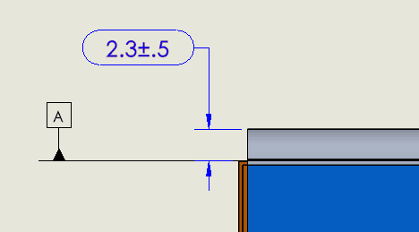
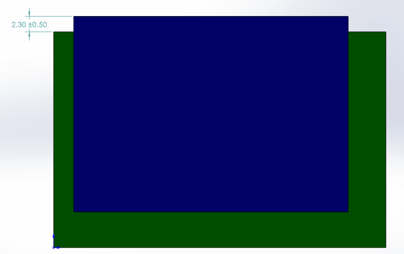
Hi. I am dimensioning a flexible component relative to a fixed datum surface (A). I want the flexible component edge to be parallel to the datum within the +-0.5mm tolerance. Does the below dimension alone ensure the ENTIRE flexible edge is within the 0.5mm tolerance? Or do I need to add a parallel geometric callout from datum A?

2021-12-28_15_04_23-SOLIDWORKS_Premium_2021_SP3.0_-_14497-01_T1_-_Sheet1___a4sn8m.png
 
A Profile of Surface tolerance control would be appropriate. 2.3 would be basic and the tolerance would be 1 for that application.
 
3DDave, thanks a lot for the quick reply. Assuming that flexible edge is tilted, does the original dimension & tolerance mean the entire edge must be within the limits or just the average of the edge? I'm not sure how to interpret what is shown.
 
With such an incomplete description of the problem I don't know how to interpret it either.
 
Keep in mind that profile across the top would control the top surface relative to datum A... which is a theoretically perfect plane formed by the tangent plane of the bottom surface. That might not be the same thing that you intended.
Also keep in mind that it's flexible, so even if you are using the ASME tolerancing standard, Rule #1 (where size automatically controls flatness and parallelism) does not apply.
 
Since it appears to not be a feature of size, rule 1 would not apply anyway.
 
Couldn't tell from the picture. Bottom line is that more info is needed.
 
Thanks a lot for the notes. I apologize for being elementary at this, I don't fully understand the appropriate way to dimension this. The blue component is silicone and the green component is aluminum. I am not worried about the overall size of the blue component, just that its top surface is within these tolerances relative to the top surface of the aluminum. The aluminum is fixed in the system and the top surface is perfectly flat. I am now thinking a geometric dimension is overkill given these are not features, but separate components. Does this help clear things up?

2021-12-29_08_37_42-SOLIDWORKS_Premium_2021_SP3.0_-_Part1___yckaox.png
 
+/- would be proper if you wanted to control size (distance between opposed points of a width or diameter). Since you control location, use profile of a surface. A tolerance is not overkill just because it's geometric. A tolerance is overkill if too tight, regardless geometric or linear.
 
Status
Not open for further replies.

Part and Inventory Search

Sponsor

Back
Top