Turning a system by 90º part 2
(OP)
thread404-468702: Turning a system by 90º
Hi,
We have already build the turning device. The post where I asked is closed
https://www.eng-tips.com/viewthread.cfm?qid=468702
I just wanted to share some pictures and say thanks to everybody


cheers,
Hi,
We have already build the turning device. The post where I asked is closed
https://www.eng-tips.com/viewthread.cfm?qid=468702
I just wanted to share some pictures and say thanks to everybody


cheers,
RE: Turning a system by 90º part 2
another day in paradise, or is paradise one day closer ?
RE: Turning a system by 90º part 2
TTFN (ta ta for now)
I can do absolutely anything. I'm an expert! https://www.youtube.com/watch?v=BKorP55Aqvg
FAQ731-376: Eng-Tips.com Forum Policies forum1529: Translation Assistance for Engineers Entire Forum list http://www.eng-tips.com/forumlist.cfm
RE: Turning a system by 90º part 2
We could have taken the net out for the picture
I wanted to have more vivid colours, but the options were very limited
RE: Turning a system by 90º part 2
another day in paradise, or is paradise one day closer ?
RE: Turning a system by 90º part 2
There are many cables, components, screws... so it is not easy to know. Below the blue plate one can see a black thin one. We have different thinknesses (of the black plates) to play with the distance
cheers,
RE: Turning a system by 90º part 2
another day in paradise, or is paradise one day closer ?
RE: Turning a system by 90º part 2
I'm afraid the two shafts might not be well aligned.
How to position the block bearings so their axes are coincident?
We have cut an aluminium L-profile to connect the shafts (the inner ends have a square section); but this doesn't not guaranty anything.
The bearings have a spherical outer surface to compensate for misalignment.
We have a self-leveling cross-line Laser (Bosch GLL 3-80 CG), so we could see from the side and top the laser on the shafts, but the lines are two thick.
What can we do to align the shafts/bearings?
How is this done normally (I mean having two bearings with a shaft is a very standard setup)?
thanks
RE: Turning a system by 90º part 2
Spherical bearings and low speed. You don't need very precise alignment.
RE: Turning a system by 90º part 2
If the shafts are not aligned there will be additional forces
It seems also difficult to place the gearbox in its position: it's heavy. It can easily tilt the shaft
Here some pictures
RE: Turning a system by 90º part 2
I know it is a bit off topic but it can be a suggestion for the future and different applications. The position of C.G. is always plumb (concrete flume) and always inside the footing base (pipe. Furthermore in such a case it is not needed even to anchor the base to the ground)
RE: Turning a system by 90º part 2
Are you referring to the diagonal braces carrying the load down the stretcher section of the frame? If so, I agree. I think the weight of gearbox could induce some twisting of the stretcher which could lead to difficulty in aligning the gearbox and the shafts even if it is a "3030" type extrusion. It might not be as clean, but a pair of vertical legs going down to the floor with adjustable leveling feet could support the gearbox directly.
I can't quite tell from the photos but is the turning assembly on casters?
Kyle
RE: Turning a system by 90º part 2
Since the bearing has this rotating feature if the axis of the gearbox is not well aligned with the axis of the shaft it will tilt it.
We could add some screws under the gearbox to place it in its theoretical position
The question is how to align them properly? How can one measure the position of both axes?
Here another side picture
The assembly turns on the two bearings. And the center of gravity is on the axis of the system. The difficulty is aligning the axes of both bearings and the gearbox
RE: Turning a system by 90º part 2
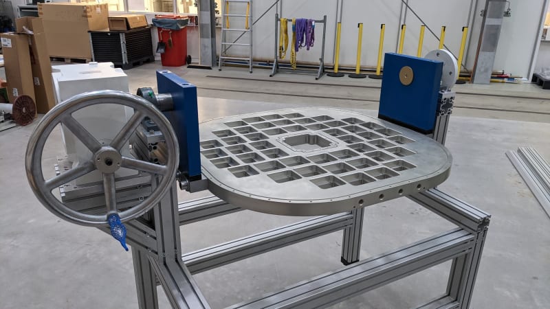
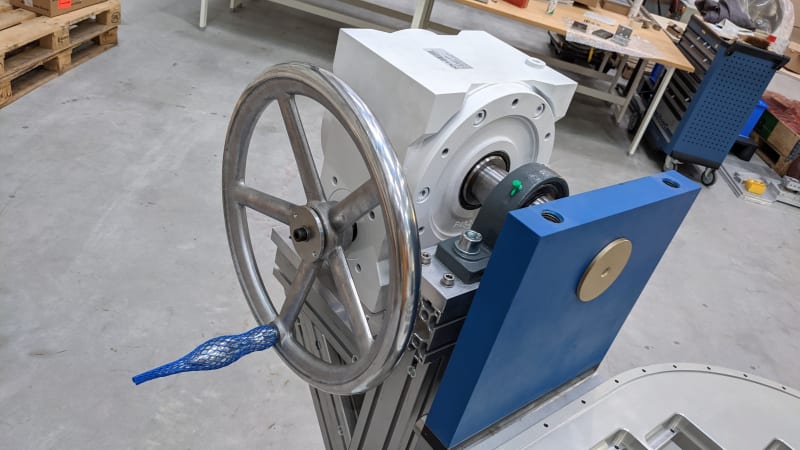
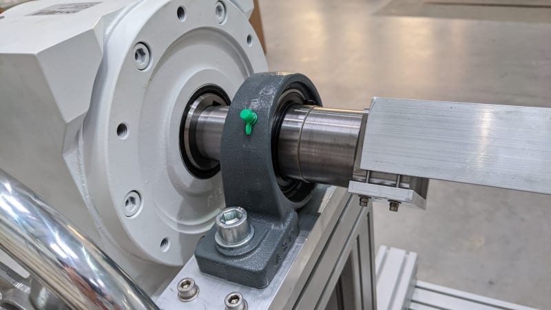
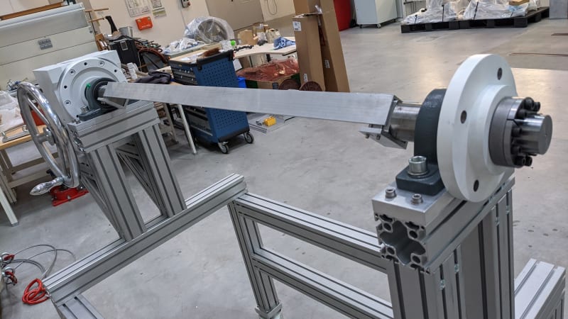
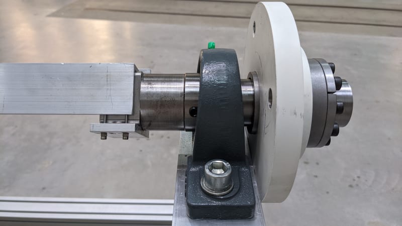
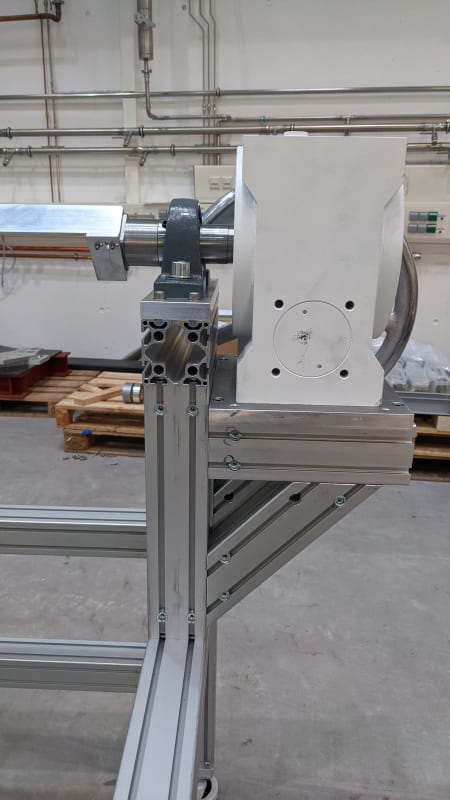
Well my first observation is that there appears to be no shims under any of the bearing mounts or gearbox, my company made steel rolling mills which had numerous fabricated frames with rollers mounted between two bearings and driven by geared motors so it was a similar set up. We always had shims to adjust the height of bearing housings and geared motors because you can’t achieve perfect alignment unless the tolerances on the machined components were so tight that it made it uneconomical to produce. In addition to the shims and where possible we built the frames up and had bearing housing pockets machined on both sides of the frame simultaneously to ensure horizontal alignment and used the shims for vertical alignment, also we used laser alignment tools and shimmed accordingly. What tolerances are specified on the component drawings that you are making this thing from?
“Do not worry about your problems with mathematics, I assure you mine are far greater.” Albert Einstein
RE: Turning a system by 90º part 2
I don't know what shims are, but OP uses aluminum extrusions, meaning the height of the gearbox can be easily adjusted, i.e. exactly aligned with the shaft.
You mount the shaft, you mount the gearbox on a shaft, and then you just put the structure underneath the gearbox. You let the shaft and gearbox dictate where the supporting structure will be, not the other way around.
RE: Turning a system by 90º part 2
The problem is the horizontal alignment.
desertfox, you wrote:
we built the frames up and had bearing housing pockets machined on both sides of the frame simultaneously to ensure horizontal alignment
Could you elaborate more that? do you have some pictures or sketches?
Scuka,
I understand shims are parts to move up or down the bearing (like a wedge, or screws)
Your assembly procedure seems logical. But the gearbox is heavy and it is not easy to inset the shaft into the gearbox hole (we need to use clamps). Since the bearing block can rotate it is not easy to align the first shaft
RE: Turning a system by 90º part 2
Bearings compensate for angular misalignment, but if they're not at 0° (which they never are, that's why these bearings are used in the first place), the end of the shaft wobbles. If there's a gearbox, it constrains the wobble, which might create problematic forces one didn't expect.
RE: Turning a system by 90º part 2
See sketch, I have a 'I' beam right hand and left hand frame joined by an 'I' beam running horizontally across, plates are also welded to the top of the'I' beam and the whole thing is mounted in a machine and the welded plates on top of the 'I' beams are machined across in one go to ensure horizontal alignment.
“Do not worry about your problems with mathematics, I assure you mine are far greater.” Albert Einstein
RE: Turning a system by 90º part 2
Or use a flange mount pillow block mounted to the left blue bracket (with a lathe dog):
https://www.mcmaster.com/pillow-blocks/mounted-bal...
RE: Turning a system by 90º part 2
We also used to machine the ends of the pillow block and make a machined fit with the pocket in the frame, so a tight clearance fit, the hole being oversized wouldn't matter then.
“Do not worry about your problems with mathematics, I assure you mine are far greater.” Albert Einstein
RE: Turning a system by 90º part 2
What about making a long bar (1450mm - 4.75 feet) sticking it in the gearbox and then position the bearings. Even with the block bearings
I have to check with our workshop if they able to produce such accurate rod. Maybe using different sections connected by dowel pins
RE: Turning a system by 90º part 2