Tek-Tips is the largest IT community on the Internet today!

Members share and learn making Tek-Tips Forums the best source of peer-reviewed technical information on the Internet!

  • Congratulations TugboatEng on being selected by the Eng-Tips community for having the most helpful posts in the forums last week. Way to Go!

The output interference of the voltage sensor is large, how to choose the filter

Status
Not open for further replies.

sunny2021

Electrical
Joined
Sep 29, 2021
Messages
2
Location
US
I use a voltage sensor to measure the sinusoidal voltage signal attached to both ends, and get messy. I want to design a low-pass filter to filter out high-frequency interference signals. The problems are as follows:
1. Is there any relationship between the cut-off frequency of the low-pass filter and the measured signal? ;
2. Is there a better filter option?
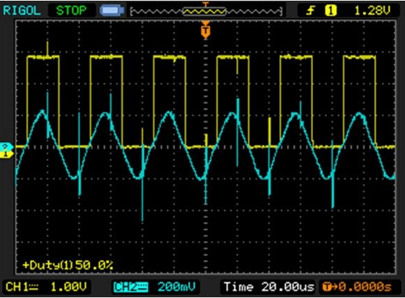
The measurement signal is shown in the figure, the blue is the waveform at both ends of the sensor, and the yellow is the output of the zero-crossing comparator.
QQ%E6%88%AA%E5%9B%BE20210929183822_ijgv59.png
 
What's to design? The spikes are so high frequency compared to the sinusoid, a cap on the input would knock it out without a problem and the comparator would do the rest...

Of course, it might make more sense to find the source of the spikes and kill those at the source.

Dan - Owner
Footwell%20Animation%20Tiny.gif
 
1. Is there any relationship between the cut-off frequency of the low-pass filter and the measured signal?
MGS is correct, a cap will knock down the spikes, but it can't be too large, or it will attenuate the desired signal as well, which goes to the cutoff frequency of the filter, the cap in this case, needs to be about 2x the highest desired frequency of the passband.

TTFN (ta ta for now)
I can do absolutely anything. I'm an expert! faq731-376 forum1529 Entire Forum list
 
looks like a couple of ferrite beads with clear up your spike problem.
 
Status
Not open for further replies.

Part and Inventory Search

Sponsor

Back
Top