Continue to Site

Eng-Tips is the largest engineering community on the Internet

Intelligent Work Forums for Engineering Professionals

  • Congratulations KootK on being selected by the Eng-Tips community for having the most helpful posts in the forums last week. Way to Go!

Buttress Reinforcement (Concrete Jacket) - Shear Flow

Status
Not open for further replies.

Redacted

Structural
Mar 12, 2016
160
Good day, I need to reinforce a buttress at the top as it is damaged and there is also not enough shear capacity at the top to transfer the force to the lower portion of the buttress.

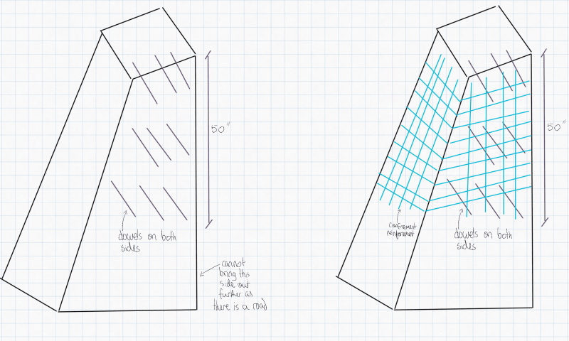
I would like to essentially jacket the existing buttress to increase the shear capacity and to transfer the force to the lower portion of the buttress. I do not want to jacket the entire column (plan to only go about 5' down from the top, the full height of the buttress is about 18'). I would just like to provide a jacket at the top to successfully transfer the force to the stronger part of the existing buttress.

I essentially would like to calculate how many dowels I need transfer this force.
I haven't done a concrete jacketing calculation before but have done shear stud designs for steel beams. I’m not sure if I am approaching this the right way so any help would be appreciated.

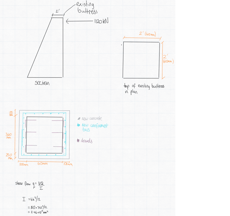
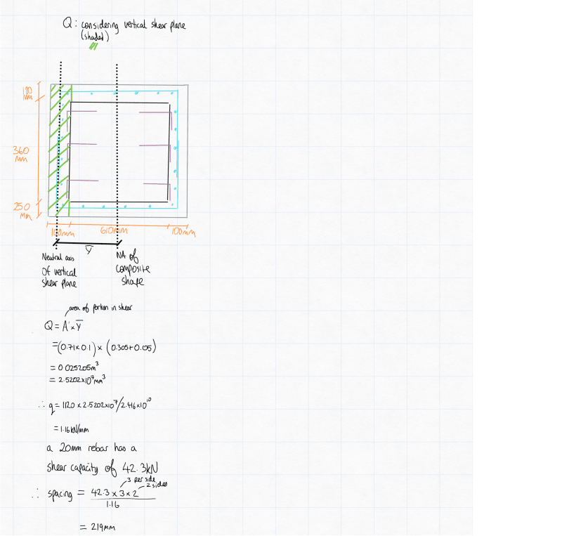
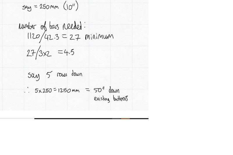
See shear flow calculations below :

eng1new_tvhvz8.png
eng2new_eigp8h.png
eng3new_khubdk.png


I am not sure how to calculate the required confinement reinforcement either? Any help on that would be helpful.

I also need to replace about 2' of concrete at the top of the buttress with new concrete. To connect the new concrete to the old, would I need additional vertical bars doweled into the existing concrete? Would these vertical bars need to take the full shear force? If so I don't think it will work as it would need 27 bars in a 2'x2' space. Or would the top 2' of new concrete just act with the new confinement bars and dowels going down the buttress to transfer the load?

I am trying to also visualise how this detail would work, as it is not going all the way down to the foundation and as it is a buttress the section will get larger the farther down you go. I don't see much literature on strengthening of buttresses so I am treating this like a column, which should be a conservative approach, as the shear capacity should increase linearly down the buttress.
 
Replies continue below

Recommended for you

Rather than trying to form and dowel into the sloped face, I would be tempted to increase the depth at the top of the buttress by doweling into the back of it (on the vertical, flat face). If you want to stick with your idea, take a look at using the shear friction concept and installing vertical dowels into the top of the buttress.
 
Thanks for the response MotorCity,

My original sketch wasn't really clear on the sides I was dowelling into, so for clarity I was planning to dowel into the sides of the buttress as shown below.

engtips_4_new_yyiaqi.png


Unfortunately, I can't really increase the depth of the flat vertical portion that I think you are referring to as it's essentially on a road and I can't reduce the road width.

With regard to your shear friction concept, do you mean something along these lines?
Engtips_5_glhafy.png


I was thinking of doing something like that originally but I assumed there would be too many bars required in the ~2'x2' space to take the 1120kN load. I guess I would need to do something like this regardless as I need to remove about 2' of bad concrete at the top?

I'll look into the shear friction concept.
 
Yes, your latest sketch is what I had in mind. Not sure if you just need to replace the bad concrete or replace the bad concrete and add additional concrete. Either way, the shear friction idea is exactly for this type of situation. If you needed additional concrete, I suppose you could dowel vertical bars into the sloped portion as well. Take a look at corbel design also. This is a corbel of sorts, turned vertical.
 
Thanks MotorCity,

I took a look at the shear friction concept. I couldn't find much information on it online but I did see some guidance in ACI 318-14

The required area of steel that I am getting is too high though :

According to ACI 318-14 the area of shear reinforcement dowels required = ultimate shear force/safety factor*coefficient of friction*yield strength of steel

Av=1120000N/0.75*0.6*400MPa

= 6222mm2

I can't see how I can fit this area of steel in the required space. I think the largest section I can get it 4'x2'. It would essentially need 20T20 bars fully developed top and bottom.

Any advice would be greatly appreciated.
 
Hi there,

I am still trying to figure out this detail.

When reviewing the shear friction concept, I believe I will need to include the shear friction reinforcement of 20T20 bars at the top regardless, to essentially clamp the new concrete top to the existing concrete below (I need to remove about 2 feet of bad concrete at the top of buttress and replace with new concrete)

I am thinking of using the shear friction reinforcement for the new concrete buttress top and still use the shear link wrap and side dowels (from first post) to transfer the forces down into the lower/stronger portion of the buttress.

I am trying to figure out how I can get the 20T20 or equivalent post installed bars to work in a 2'x2' space (plan area gets larger the lower down you go but conservatively assuming 2'x2').

I am planning to use HILTI's HY 200 epoxy for the post installed bars.

I essentially would like some advice on best practice for a detail (or alternative ideas for a simpler one) like this as I haven't done this before. I would like to determine what the minimum spacing needs to be and if concrete breakout needs to be considered when designing shear friction reinforcement.

I took a look at HILTI's design tables. The tables are referencing ACI 318-14 Chapter 17, which is for concrete anchors. Are the edge and clear spacing tables here applicable for shear friction reinforcement?

Based on the table I would consider the maximum effective embedment of 15"

engtips_breakout_2_dzhbs5.png


If I can utilise a clear spacing between rebar of 3 3/4" and edge spacing of 3 3/4" I can prob get a reinforcement arrangement of 20T20 to work.

Any help would be greatly appreciated as I would like to firm up a draft detail for discussion with a colleague.
 
Redacted said:
If I can utilize a clear spacing between rebar of 3 3/4" and edge spacing of 3 3/4"...

Don't count on being able to drill at precise locations. Existing rebar will interfere fairly often, forcing relocation of planned holes.

To salvage a damaged structure that will be subjected to high load (1120kN), assemble as much info on the existing structure as possible:

1) Preferably as-built or original drawings, if not available, make detailed measurements of all accessible dimensions and features then make drawings.

2) Detailed mapping of visible damage.

3) Report on existing concrete condition including compressive strength.

 
Hi SlideRuleEra,

You raise some helpful points

1)Unfortunately as built/original drawings do not exist. I did make as many detailed measurements as possible on site.

2)Notes were made from what was visible. After demolition of the top 2' of existing concrete the condition will be made more apparent.

3)This was tricky for this project, I had a colleague carry out a rough concrete rebound test with a schmidt hammer. It confirmed my assumption of 2500 psi. My colleague also carried out a rebar location exercise and surprisingly the rebar locator did not pick up any rebar in the buttress. I guess that will also be made apparent after demolition works.
 
Redacted said:
1) After demolition of the top 2' of existing concrete the condition will be made more apparent.

2) ...concrete rebound test with a schmidt hammer... confirmed... 2500 psi.

3) ...rebar locator did not pick up any rebar in the buttress.

Make use of this information:

1) From your other thread on this subject, 2' is barely below the bottom the strut that fractured the buttress. Take off more than 2', a lot more... because:

2) 2500 psi concrete will be the limiting factor on repair. Taking off more than 2' will make available a lot more surface area to bond new concrete to old. Concerning bonding... T20 rebar, why so "small"? The buttress is pretty massive (2' thick). At least look into using larger rebar, there will be pros and cons. Also a structurally effective bond can be achieved directly between old and new concrete, it the proper procedures are used.

3) Everything about this buttress points to 1920s design / construction (Despite the assumption in the other thread that it is 50 years old.) There may not be any rebar, need to find out sooner rather than later. If no rebar, you may have to decide if the entire buttress should be replaced.

 
Hi SlideRuleEra and thanks again for your helpful comments.

1+2) You are correct, I doubled the amount to take off, which doubled the surface area available for the installation of the shear friction dowels and increased the surface bond area. I ended up increasing to T25 bar, as I only need 13 of these as per the shear friction calculation, which I can fit quite comfortably in the space.

3) Yes, I believe it is quite an old buttress and the make up of it will become more apparent during the demolition works. The client stated that they don't want to replace the buttresses, so I am kind of doing this design as a somewhat temporary fix(until the buttress and adjacent retaining walls need to be replaced). I will include a caveat that this repair is still dependent on the existing buttress working as originally intended, which I don't think is unreasonable as the loads are not increasing with the new strut that I am putting in. I am effectively trying to beef up the top of the buttress so that the axial compression load from the strut can safely get transferred to the lower portion of the buttress.

I am relying on two methods of transferring the shear here (each should independently be able to transfer the load, although I've added in the redundancy just in case).

- Shear friction, with the vertical dowels, clamping the new and old concrete interface
- Concrete jacket for shear flow through the side dowels

This is a plan cross-section through the buttress of what I was thinking :

ButtressET1_fimfiu.png


Any advice would be appreciated.
 
Your shear stress calculation is only valid if the applied load is in the direction shown below:
Shear_Stress_Calculation_n4lipo.png

It appears that your applied load is actually perpendicular to this. (If I'm understanding things correctly, the plan showing the dowels is rotated 90 degrees from the section/elevation that shows the taper.)

Structural Engineering Software: Structural Engineering Videos:
 
Redacted said:
1) I doubled the amount to take off, which doubled the surface area available for the installation of the shear friction dowels and increased the surface bond area.

2) I ended up increasing to T25 bar, as I only need 13 of these as per the shear friction calculation, which I can fit quite comfortably in the space.

1) Good, that should get the cutoff line below the fractured area. Taking off more than that will help, too.

2) I'll be your Dutch uncle for a little while... this is not a pristine design project where the goal is to optimize all components. It's a repair where existing conditions are only vaguely understood, and anything that can be done is controlled by those exiting conditions. Don't stop at 13 each T25 bars because calcs say that is what is needed, put as many bars as will comfortably fit, making sure it is at least 13. And fill the available footprint, not just the perimeter. Here is an example of "vague existing conditions":

Your calcs are all for shear. In addition to shear, at the same time, loading is applying tension to some of the rebar to resist overturning of the "new" concrete. Exactly how this tension will be distributed among the bars (already carrying shear load) is certainly vague. Also, how the (estimated) 2500 psi concrete will react to compression from overturning force is a guess.

Redacted_-_Uplift-500_i0naik.png


Dutch uncle hat put away.

 
@ProgrammingPE Thanks you are right; I've actually changed the geometry around quite a bit (eg 203mm jacket all around instead of 100mm), and now that I am removing more of the wall and replacing it with new concrete, the cross-section at the 4' mark down is larger, which is resulting in a reduction in the shear dowels required per row or allowing for larger spacing. However, your comment is very helpful, as I initially was thinking that I can put the shear dowels through only the two faces as shown above, but it seems that the shear is acting in all planes and I need the shear flow reinforcement in all faces normal and parallel to the force. Now I need to figure out how to fit additional bars in to account for this.

@SRE yes that's true and please do keep the dutch uncle hat on, I appreciate the assistance. You raise a good point and it's one of the reasons why I didn't want to just trust the shear friction reinforcement (this is another reason why I am also putting a concrete jacket around the buttress). I guess removing more is a double-edged sword as you would be increasing the potential moment at the joint. My understanding of shear friction reinforcement is that the reinforcement would need to fully develop with rebar that is already in the buttress. However, if no rebar exists the dowels would need to act as anchors (considering concrete breakout etc). Not sure if that thought process is correct, so if anyone can comment on that, it would be helpful.

I'm thinking that the concrete jacket reinforcement will effectively confine the existing buttress, which should assist with providing overturning restraint.

For clarity the top 4' of the existing buttress will be removed and replaced with a newly poured RC cross-section like this (dashed white line is the existing buttress) :

Buttresset2_jdqlla.png


Reinforcement inside the white dashed line are the 15 T25 dowels. Reinforcement outside the white lines are the confinement reinforcement.

The jacket rebar will extend all the way to the top of the buttress replacement, as will the shear friction vertical dowel reinforcement.

The RC jacket will extend an additional 4'6" down from the new concrete/old concrete joint, and in this location shear dowels on the sides will connect the jacket to the existing.

I'm not sure if that is confusing? If so I can provide a sketch.

One bit of confusion that I had with the confinement vertical reinforcement is that it will only be on the top (8'6") of the buttress (therefore not tying into any foundation reinforcement. So I guess the only purpose it can serve is to confine the concrete. The total buttress height is assumed to be approximately 16', so putting the jacket around about half. As stated before though, I am just trying to transfer the load safely into a stronger portion of the buttress because the top 2' was bad concrete.

The client doesn't want to replace the entire buttresses or go deeper than the 8'6" mark, as this will require extensive works below grade.
 
Redacted - IMHO, you are on the right track now. As I mentioned yesterday, "2500 psi concrete will be the limiting factor on repair." You are distributing connections to the existing concrete over a large part of the 2500 psi concrete surface area... successfully moving away from reliance on a few, closely grouped and heavily loaded connection points. You have even convinced me that the concrete collar is a good idea (to contain the existing 2500 psi concrete). Until now, frankly, even though I didn't say anything I thought the collar was at best a waste of time (and your client's money) or at worst tending to make "Swiss cheese" out of the existing concrete.

Right now, I'll suggest to take the appropriate steps (total cleaning, soak for 24 hr., place new concrete) to get a structural bond between new & old concrete. I don't know how effective this will be with the 2500 psi concrete, but it's worth a try. We used this bonding method to restore the turbine-generator pedestal of one of our units that "blew up"... think repairing concrete where 4" diameter, 6 feet long embedded anchor bolts broke out of the reinforced, solid 4000+ psi concrete pedestal.

Also, consider hydrodemolition. Compared with impact demolition, this will prevent fracturing existing concrete that will not be removed. A second benefit is to preserve existing rebar (if any). Don't remove any more existing rebar than absolutely necessary... reincorporate it back into the new concrete... in addition to your planned modifications.

 
Status
Not open for further replies.

Part and Inventory Search

Sponsor